QR Code

Products
Contact Us


Fax
+86-574-87168065

Email

Address
Luotuo Industrial Area, Zhenhai District, Ningbo City, China


On a busy construction site, a mobile crane lifts a precast beam while the operator holds the load at height. The boom cylinder is not moving, but it is working. It is holding several tonnes against gravity, and the only thing preventing the load from drifting downward is the hydraulic pressure trapped inside the cylinder. A small leak at the rod seal or the piston seal does not announce itself with a burst. It appears as a slow film of oil on the rod, a gradual loss of holding pressure, or a boom that creeps down a few centimetres over an hour. In a crane, that slow leak is a serious event, because the load is above people and equipment. Leakage prevention is therefore not a maintenance preference. It is a design priority that determines whether the machine can hold a load safely and whether the operator can trust the cylinder throughout the lift.
The design priority is shaped by the operating conditions of a mobile crane. The cylinder works at high pressure, it is exposed to dust and weather, it is subjected to vibration and side loads, and it must hold position for long periods without drifting. Our factory at Raydafon Technology Group Co.,Limited designs Mobile Crane Hydraulic Cylinders around these conditions, and the guidance below explains why leakage prevention drives the seal system, the surface finish, the assembly process, and the test program. It also explains how procurement teams can verify that a cylinder will hold its seal in service, not just at the factory gate.
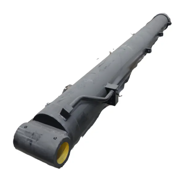
A leak in a crane cylinder rarely begins at the point where oil is first seen. The visible oil is the end of a path that starts at a seal interface, a surface defect, or a threaded connection. There are five leakage paths that matter in a Mobile Crane Hydraulic Cylinders design, and each one has a different mechanism. The first is the rod seal path. The rod moves in and out of the cylinder, and the rod seal must wipe the rod clean while holding pressure. Dust and grit that pass the wiper can abrade the seal lip and the rod surface, creating a path for oil. The second is the piston seal path. The piston seal separates the extend and retract chambers, and it must hold pressure in both directions. If the seal extrudes into the clearance gap under pressure, the leak begins at the extrusion point. The third is the static seal path at the end cover and the port block. These seals do not move, but they are compressed by the assembly torque, and they can take a compression set over time. The fourth is the port and fitting path. The threaded connection can loosen under vibration, and the seal at the port can be damaged during installation. The fifth is the cylinder tube and rod surface path. A scratch, a corrosion pit, or a coating defect can create a leak path that no seal can compensate for.
The table below maps these paths to the conditions that drive them and the design response that prevents them.
| Leakage Path | Driving Condition | Design Response | Procurement Evidence |
| Rod seal | Rod movement, dust, side load | Lip seal with dust wiper, chrome or ceramic rod | Seal specification, rod finish data |
| Piston seal | High pressure, extrusion gap | Anti-extrusion ring, tight groove tolerance | Groove dimension report, seal data |
| Static seal | Assembly torque, thermal cycling | O-ring with controlled compression, smooth groove | O-ring material, groove finish data |
| Port and fitting | Vibration, installation torque | Locking feature, correct port seal | Port specification, torque procedure |
| Tube and rod surface | Impact, corrosion, abrasion | Coating, surface finish control, protection | Coating thickness, salt spray report |
The path that dominates in service depends on the application. A crane working in a dusty quarry will stress the rod seal and the wiper. A crane working near the coast will stress the rod coating and the static seals. A crane that performs many load-holding operations will stress the piston seal and the anti-extrusion ring. Our engineering team reviews the duty cycle and the environment before selecting the seal system for each Mobile Crane Hydraulic Cylinders project. Our factory maintains the seal and surface data for each design, so that the leakage path analysis is documented rather than assumed. The goal is to prevent the leak at the path where it is most likely to start, not to rely on a generic seal package.
For a buyer, the leakage path table is a useful review tool. A supplier that can explain which path dominates in the intended application is a supplier that has analyzed the design. A supplier that provides only a seal brand name is a supplier that has not connected the seal to the path. The procurement team should ask for the seal specification and the surface finish data for the rod, the tube, and the grooves, because these are the parameters that determine whether the paths are closed.
The reconstruction below follows a typical load-holding failure on a mobile crane. The sequence is not unusual, and it shows why a small leak is treated as a critical design issue rather than a minor maintenance item.
The failure is not caused by a single event. It is caused by a chain of small effects that interact. The dust that passes the wiper abrades the rod seal. The abraded seal leaks oil. The leaking oil reduces the holding pressure. The reduced holding pressure is compensated by the control system, which raises the oil temperature. The higher temperature thins the oil and accelerates the leak. The chain is the reason leakage prevention is a design priority. If the wiper and the rod finish are designed to exclude dust, the chain does not start. If the piston seal has an anti-extrusion ring, the second path does not open. If the rod coating resists abrasion, the rod surface does not degrade. The design priority is to break the chain at the earliest possible link.
The load-holding consequence is more serious than a simple oil loss. A crane cylinder that drifts under load can lower the load without a command, and the operator may not have time to react. The drift can also change the load radius, which affects the crane's stability. In a worst-case scenario, the drift can lead to a load drop or a tip-over. These consequences are why the design priority is not only about oil containment. It is about controlling the load. Our factory treats the load-holding function as the primary requirement in the Mobile Crane Hydraulic Cylinders we design, and our testing includes a holding test that measures the drift over a defined period. Our customers receive the holding test data with the cylinder documentation, so that the load-holding performance is verified before the crane is placed in service.
For a buyer, the load-holding test is the specification that connects the seal design to the crane safety case. A supplier that provides only a static pressure test is a supplier that has verified the burst strength but not the holding behavior. The procurement team should request the holding test procedure and the acceptance criterion, and should confirm that the test is performed at the rated pressure and the rated temperature.
The seal is not a single ring. It is a system of geometries and surfaces that work together, and the leakage prevention depends on the fit between them. The rod seal system typically includes a primary lip seal, a buffer seal, and a dust wiper. The primary lip holds the pressure. The buffer seal protects the primary lip from pressure spikes. The dust wiper removes grit from the rod before it reaches the primary lip. The piston seal system includes a primary seal and an anti-extrusion ring. The anti-extrusion ring closes the clearance gap under pressure and prevents the seal from extruding. The static seals include the end-cover O-ring and the port seal, and their performance depends on the groove dimensions and the compression. The table below maps the design decision to the leakage mechanism it controls.
| Design Decision | Leakage Mechanism Controlled | Typical Specification | Procurement Check |
| Rod seal lip geometry | Oil film control, pressure holding | Single or double lip, spring energized | Seal data sheet and groove drawing |
| Dust wiper design | Dust ingress and rod abrasion | Polyurethane wiper with dirt exclusion lip | Wiper material and test report |
| Piston anti-extrusion ring | Seal extrusion at high pressure | PTFE or POM ring, tight gap | Groove tolerance and ring material |
| Rod surface finish | Seal wear and leak path | Ra 0.2 to 0.4 micrometre, hard chrome | Surface finish report and coating thickness |
| Tube bore finish | Piston seal wear and leakage | Honed bore, Ra 0.2 to 0.4 micrometre | Bore report and roundness data |
| Groove corner radius | O-ring damage during assembly | Rounded corner, burr free | Visual and dimensional inspection |
The rod surface finish is one of the most important decisions, and it is often the least visible. A rod that is too rough will abrade the seal lip. A rod that is too smooth can prevent the formation of the micro-film that lubricates the lip, and the seal can run dry. The correct finish is a controlled roughness that supports the oil film and minimizes wear. The coating is equally important. Hard chrome plating provides wear resistance and corrosion resistance, and a ceramic coating provides even higher wear resistance for abrasive environments. The coating thickness and the bond strength determine whether the coating survives the rod movement without chipping or spalling. Our factory specifies the rod finish and the coating for each Mobile Crane Hydraulic Cylinders application, and our factory verifies the finish and the thickness before assembly. The goal is to make the rod surface a controlled part of the seal system, not a commodity surface.
The groove dimensions are the other half of the seal system. The groove width, the groove depth, and the corner radius determine the seal compression and the seal support. A groove that is too shallow will over-compress the seal and accelerate wear. A groove that is too deep will under-compress the seal and allow leakage. A sharp corner will damage the O-ring during assembly. The procurement team should request the groove drawing and the dimensional inspection report, because these are the parameters that determine whether the seal will sit correctly in the cylinder. A supplier that provides the seal part number but not the groove data is a supplier that is leaving the fit to chance.
The seal material selection is the final decision in the system. NBR is the standard for general hydraulic oil, and it offers good wear resistance at moderate temperatures. Polyurethane offers higher wear resistance and is used for rod seals in abrasive environments. PTFE is used for anti-extrusion rings and for low-friction applications. FKM is used for high-temperature applications. The material must be compatible with the hydraulic oil and the operating temperature, and it must be matched to the surface finish and the groove geometry. The table in the next section provides the product parameters that tie these decisions together.
A cylinder that passes a static pressure test can still leak in service, because the static test does not reproduce the rod movement, the thermal cycling, or the side load. The manufacturing and test practices must therefore be designed to verify the leakage prevention under conditions that are closer to the application. The process below follows the sequence that our factory uses for Mobile Crane Hydraulic Cylinders, from cleaning to final documentation.
The table below provides the key product parameters for our Mobile Crane Hydraulic Cylinders, and it shows how the parameters connect to the leakage prevention requirement.
| Parameter | Typical Specification | Leakage Prevention Role |
| Bore diameter | 50 to 320 mm | Determines the seal size and the extrusion gap |
| Rod diameter | 30 to 220 mm | Determines the rod seal and the wiper size |
| Rated pressure | Up to 350 bar | Sets the seal pressure rating and the test pressure |
| Rod surface finish | Ra 0.2 to 0.4 micrometre | Controls seal wear and oil film formation |
| Rod coating | Hard chrome 20 to 30 micrometre or ceramic | Protects the rod from abrasion and corrosion |
| Tube bore finish | Honed, Ra 0.2 to 0.4 micrometre | Controls piston seal wear |
| Seal material | NBR, polyurethane, PTFE, FKM | Matches the oil and the temperature |
| Static leak test | 1.5 times rated pressure, 10 minute hold | Verifies the static seals and the assembly |
| Holding drift test | Rated load, 30 minute hold, drift limit specified | Verifies the load-holding function |
The test practices are the evidence that the design and the manufacturing are correct. A cylinder that passes the static leak test but has no holding drift test is a cylinder whose load-holding behavior is unverified. A cylinder that passes the holding test but has no cycle test is a cylinder whose seal endurance is unverified. Our factory at Raydafon Technology Group Co.,Limited performs the full sequence for the Mobile Crane Hydraulic Cylinders we supply, and our factory provides the test reports with the cylinder. The goal is to make leakage prevention a measured property, not a claim.
Procurement should evaluate leakage prevention as a set of evidence, not as a single specification. The evaluation should cover the design, the materials, the manufacturing controls, the test reports, and the after-sales support. The checklist below provides the questions that a buyer should ask before placing an order, and the acceptance criteria that a reliable supplier should meet.
| Evaluation Area | Question to Ask | Evidence to Request | Acceptance Criterion |
| Design | Which leakage paths were analyzed for this application? | Design review and seal system description | All five paths are addressed |
| Materials | Which seal materials and rod coatings are specified? | Material certificates and coating data | Matched to oil, temperature, and environment |
| Manufacturing | How are groove dimensions and surface finish controlled? | Inspection records and process control plan | Within drawing tolerance for every batch |
| Testing | Is a holding drift test performed in addition to the static test? | Test procedure and test report | Drift within the specified limit |
| Documentation | Are the test reports and material certificates shipped with the cylinder? | Documentation package | Complete and traceable to the serial number |
| After-sales | What seal kit and support are available for field repair? | Seal kit part number and service guide | Available and documented |
The evaluation should also include a review of the supplier's production control. A design that is correct on paper can be compromised if the groove is machined with a worn tool, if the seal is installed with a damaged tool, or if the torque is applied without calibration. The procurement team should ask how the supplier controls these steps and whether the control records are available for review. A supplier that can show the control records is a supplier that is managing the leakage prevention in production, not just in the design.
Our factory at Raydafon supports procurement teams with the design review, the material certificates, the test reports, and the seal kit data for the Mobile Crane Hydraulic Cylinders we supply. Our factory also welcomes customer audits and can provide samples for evaluation. The goal is to make the evaluation transparent and to give buyers the evidence they need to confirm that the cylinder will hold its seal in service.
For a buyer, the most useful question is often the simplest. Ask the supplier to explain what happens to the cylinder if the rod seal wears and the wiper fails. A supplier that can describe the failure progression and the design features that slow it down is a supplier that understands leakage prevention. A supplier that answers with a seal brand name only is a supplier that has not connected the design to the failure. The difference is the difference between a verified cylinder and a hopeful one.
Question 1: Why is a small oil film on a crane cylinder rod considered a critical warning?
Answer: A small oil film indicates that the rod seal is passing oil and that the wiper may be allowing dust to reach the seal lip. In a load-holding crane cylinder, the film can progress to a measurable drift under load, which affects the stability of the lift. The film is an early indicator of the failure chain that leads to load-holding loss, so it should be investigated before it becomes a larger leak.
Question 2: What is a holding drift test and why is it important for mobile crane hydraulic cylinders?
Answer: A holding drift test pressurizes the cylinder with a load applied and measures how far the rod moves over a defined period. It verifies that the piston seal and the rod seal can hold the load without drifting. A static pressure test verifies burst strength but does not reproduce the load-holding condition. The holding drift test is important because load holding is the primary function of a crane cylinder.
Question 3: Which seal material is best for a mobile crane hydraulic cylinder?
Answer: The best seal material depends on the oil, the temperature, and the environment. NBR is suitable for general hydraulic oil at moderate temperatures. Polyurethane offers higher wear resistance for abrasive conditions. PTFE is used for anti-extrusion rings and low-friction applications. FKM is used for high temperatures. The material should be selected with the rod finish and the groove geometry, not in isolation.
Question 4: How does rod surface finish affect leakage prevention?
Answer: The rod surface finish controls the oil film that lubricates the seal lip and the wear rate of the seal. A finish that is too rough abrades the lip. A finish that is too smooth can prevent the oil film from forming. The correct finish is a controlled roughness, typically Ra 0.2 to 0.4 micrometre, combined with a hard coating that resists abrasion and corrosion. The finish and the coating are part of the seal system.
Question 5: What documentation should I request to verify leakage prevention before ordering?
Answer: Request the seal system design review, the seal and coating material certificates, the groove and surface inspection records, the static leak test report, the holding drift test report, and the seal kit data. The documents should be traceable to the cylinder serial number. A supplier that provides this package is a supplier that has made leakage prevention a verifiable specification.
Leakage prevention is a critical design priority for Mobile Crane Hydraulic Cylinders because the cylinder is a load-holding device. A small leak can progress to a holding drift, and a holding drift can affect the stability of the lift. The design priority is expressed through the seal system, the rod and bore surface finish, the coating, the groove geometry, and the assembly controls. The verification is expressed through the static leak test, the holding drift test, the cycle test, and the documentation package. Our factory at Raydafon designs and tests our Mobile Crane Hydraulic Cylinders around these requirements, and our factory provides the evidence that procurement teams need to confirm the performance. If you are sourcing cylinders for a mobile crane application, contact our team to discuss the load-holding requirement and the leakage prevention documentation for your project.
Contact Raydafon Technology Group Co.,Limited today to discuss your Mobile Crane Hydraulic Cylinders requirements and to request the leakage prevention design and test documentation for your application.
+86-574-87168065
Luotuo Industrial Area, Zhenhai District, Ningbo City, China