
QR Code

Products
Contact Us


Fax
+86-574-87168065

Email

Address
Luotuo Industrial Area, Zhenhai District, Ningbo City, China


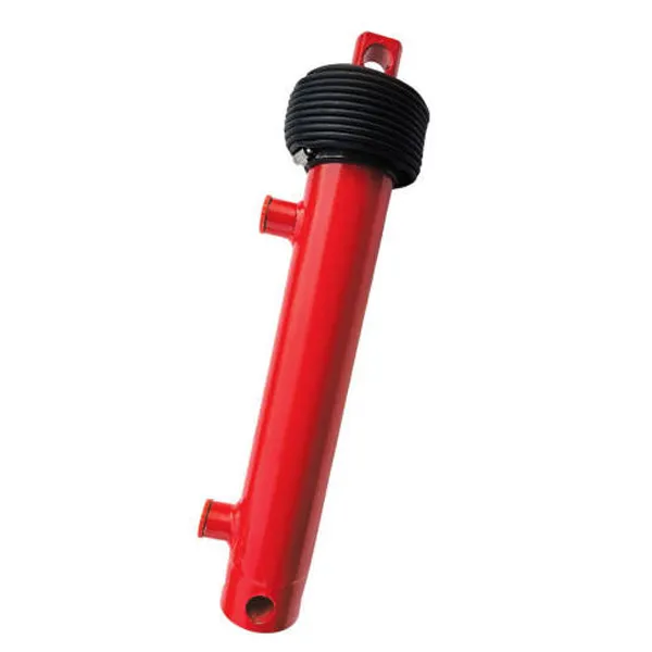
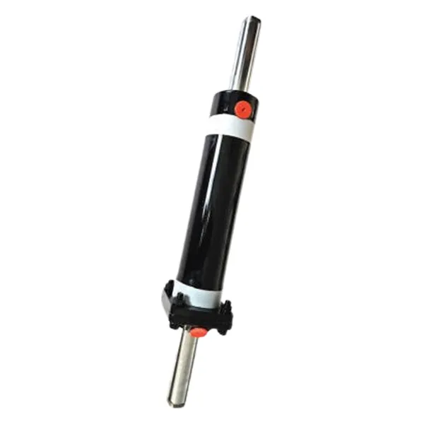
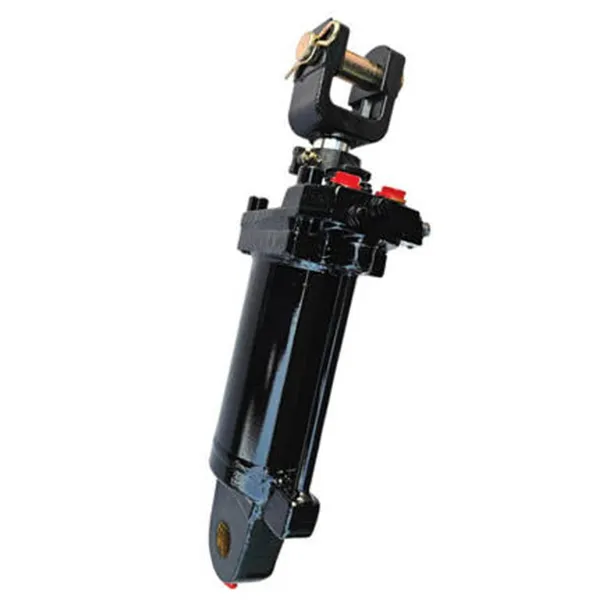
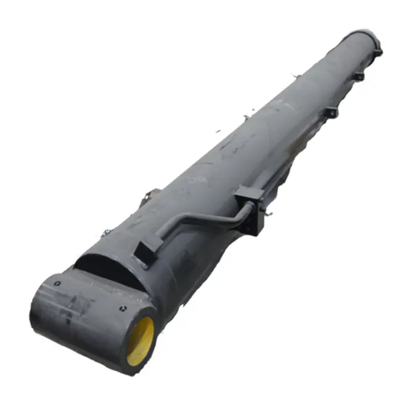
On a rear-loading refuse truck, the compaction mechanism is the component that turns a loose pile of waste into a dense, transportable load. The mechanism is driven by hydraulic power, and the component that converts that hydraulic power into the linear motion of the compaction plate is the garbage truck hydraulic cylinder. When a collection crew empties bins into the hopper, the cylinder extends, pushing the compaction plate through the load and pressing it against the body. When the plate reaches the end of its stroke, the cylinder retracts, and the cycle repeats. The force required is substantial, the cycle is repeated hundreds of times per shift, and the environment is abrasive and corrosive. For a procurement manager sourcing a garbage truck hydraulic cylinder, understanding how the cylinder powers the compaction mechanism is the basis for specifying a component that will survive the duty.
This guide is written for buyers who are responsible for sourcing hydraulic cylinders for rear-loading refuse bodies. It explains the power path from the pump to the compaction plate, the cylinder parameters that determine force and cycle time, the failure modes that appear in service, the criteria for matching a cylinder to a body builder's requirements, and the maintenance practices that protect cylinder life. The information is presented from a procurement perspective, so that buyers can ask the right questions and evaluate supplier data with confidence. Our factory at Raydafon Technology Group Co.,Limited supplies a garbage truck hydraulic cylinder for rear-loading compaction applications, and the technical points below reflect the standards we apply to the cylinders we manufacture.
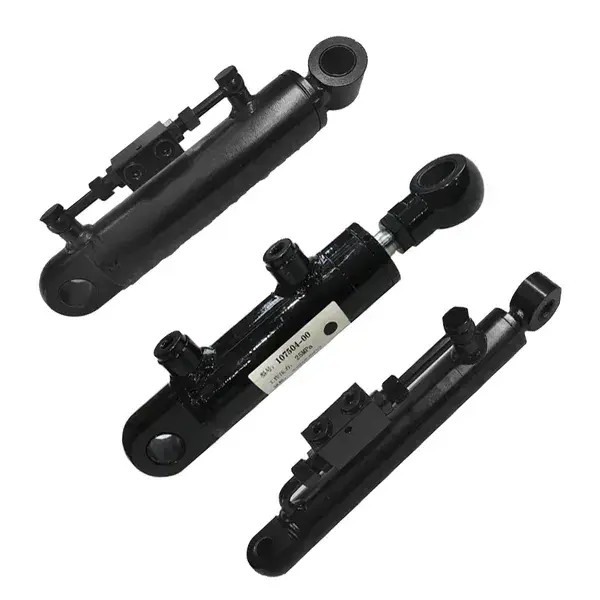
The power path begins at the truck's power take-off, which drives the hydraulic pump. The pump draws oil from the reservoir and delivers it at pressure to the control valve. The control valve directs the flow to the compaction cylinder, and the cylinder converts the pressure into linear force. The force moves the compaction plate along its guide rails, and the plate compresses the refuse against the body. When the plate reaches the end of the stroke, the valve reverses the flow, and the cylinder retracts. The cycle is controlled by the operator or by an automatic compaction sequence. The table below is not used here because the path is better understood as a sequence of stages. The stages are described in the list below.
At Raydafon, our factory designs the garbage truck hydraulic cylinder around this power path. We match the bore, the rod, the stroke, and the mounting to the compaction mechanism geometry, and we specify the seals and the surface protection for the refuse environment. The goal is to provide a cylinder that delivers the required force at the required cycle time without overheating or leaking.
For a buyer, the power path is the first thing to discuss with the body builder. The cylinder cannot be selected in isolation. It must match the pump pressure, the valve flow, the compaction plate geometry, and the body structure. A cylinder that is correctly sized for force but incorrectly sized for flow will produce a slow cycle. A cylinder that is correctly sized for flow but incorrectly sized for force will stall under a heavy load. The power path is the framework for the selection.
Compaction force is determined by the bore diameter and the operating pressure. Cycle time is determined by the flow rate, the stroke length, and the valve configuration. The two requirements interact. A larger bore produces more force but requires more oil to fill, which increases cycle time for a given pump flow. A longer stroke increases the travel of the plate but also increases the volume of oil required. The procurement team must therefore specify the force and the cycle time together, not separately. The table below summarizes the parameters and their typical ranges for a rear-loading compaction cylinder.
| Parameter | Typical Range | Effect on Compaction | Procurement Check |
| Bore diameter | 100 - 180 mm | Determines force at a given pressure | Confirm required force and pressure |
| Rod diameter | 60 - 120 mm | Determines retract force and buckling resistance | Confirm stroke and mounting |
| Stroke length | 600 - 1,500 mm | Determines plate travel and cycle volume | Confirm hopper and body geometry |
| Rated pressure | 180 - 250 bar | Determines force and stress on components | Confirm pump relief setting |
| Flow rate | 60 - 150 L/min | Determines cycle speed | Confirm pump and valve capacity |
| Mounting | Clevis, trunnion, flange | Determines alignment and load path | Confirm body builder interface |
| Seal material | Polyurethane, PTFE, NBR | Determines contamination and temperature resistance | Confirm operating environment |
| Rod surface | Hard chrome, ceramic | Determines wear and corrosion resistance | Confirm exposure to leachate and grit |
At our factory, we manufacture the garbage truck hydraulic cylinder with bore sizes, stroke lengths, and mounting configurations that match the body builder's drawings. We provide the force calculation and the cycle time estimate for each configuration, so that the buyer can confirm the performance before the order is placed. We also specify the seal material and the rod surface for the refuse environment, because leachate and grit are the two most common causes of premature cylinder wear.
For a buyer, the practical selection process is to obtain the required force and cycle time from the body builder, then calculate the bore and the flow that meet both. The force is pressure multiplied by piston area. The cycle time is the volume of oil required divided by the flow rate. If the calculated bore and flow do not match the available pump, the body builder and the cylinder supplier must agree on a compromise. The earlier this discussion takes place, the lower the risk of a cylinder that is correctly sized on paper but unsuitable in service.
Rear-loading compaction cylinders fail for reasons that are specific to the application. The environment is abrasive, the cycle is frequent, and the load is variable. The most common failure modes are seal leakage, rod corrosion, rod bending, and barrel wear. Seal leakage is usually caused by contamination or by heat. Refuse trucks operate in dust and grit, and the rod seal is the first line of defense. If the wiper seal is damaged or the rod is scratched, the grit enters the cylinder and damages the piston seal. Rod corrosion is caused by leachate, salt, and moisture. The chrome surface can pit, and the pits then damage the seal as the rod moves. Rod bending is caused by side loading or by a misaligned compaction plate. Barrel wear is caused by contaminated oil or by a worn piston guide. The table below maps the failure modes to their causes and to the procurement controls that reduce the risk.
| Failure Mode | Root Cause | Procurement Control |
| Seal leakage | Contamination, heat, damaged rod | Specify wiper seal and rod protection |
| Rod corrosion | Leachate, salt, moisture | Specify hard chrome or ceramic coating |
| Rod bending | Side load, misalignment | Confirm mounting and guide alignment |
| Barrel wear | Contaminated oil, worn guide | Specify filtration and guide rings |
| Overpressure damage | Relief valve set too high or blocked | Confirm relief setting with body builder |
At Raydafon Technology Group Co.,Limited, our factory addresses these failure modes in the design of our garbage truck hydraulic cylinder. We use a double-lip wiper seal to exclude grit, a hard chrome or ceramic rod coating to resist leachate, and guide rings to maintain alignment. We also specify the relief valve setting with the body builder so that the cylinder is protected from overpressure. The goal is to reduce the failure modes that appear most often in service.
For a buyer, the failure modes are a useful input to supplier qualification. Ask the supplier which wiper seal and rod coating are used, and ask for the relief valve recommendation. A supplier that can explain the failure modes and the countermeasures is a supplier that understands the application. A supplier that provides only a catalog page is a supplier that is not engaged with the service conditions.
Matching the cylinder to the body builder's requirements is a process of confirming the interface, the performance, and the environment. The interface includes the mounting type, the pin diameter, the port size, and the hose routing. The performance includes the force, the stroke, the cycle time, and the relief setting. The environment includes the exposure to leachate, grit, and temperature. The table below provides a decision matrix that buyers can use to organize the matching process.
| Requirement | Information Needed | Supplier Confirmation | Risk if Not Confirmed |
| Mounting interface | Clevis or trunnion drawing, pin diameter | Dimensional drawing | Installation delay or misalignment |
| Force and stroke | Required compaction force and plate travel | Force calculation and stroke confirmation | Stall or incomplete compaction |
| Cycle time | Pump flow and valve configuration | Flow and speed estimate | Slow cycle or overheating |
| Relief setting | Body structural limit and pump relief | Recommended relief setting | Overpressure damage |
| Environment | Leachate, grit, temperature range | Seal and coating specification | Corrosion and seal failure |
At our factory, we provide the dimensional drawing, the force calculation, the flow estimate, and the seal and coating specification for every garbage truck hydraulic cylinder we supply. We work with the body builder to confirm the mounting interface and the relief setting before production. The goal is to remove the interface risk before the cylinder is manufactured, because a change after production is costly and delays the vehicle build.
For a buyer, the decision matrix is a practical procurement tool. It turns the matching process into a set of confirmations that can be documented and tracked. A supplier that can provide each confirmation is a supplier that is prepared to support the build. A supplier that cannot provide the confirmations is a supplier that is likely to create a problem at installation.
Inspection and maintenance protect cylinder life by detecting the early signs of wear before they become failures. The rear-loading compaction cylinder is exposed to grit and leachate, so the inspection should focus on the rod surface, the wiper seal, the hydraulic oil, and the mounting. The maintenance should focus on cleaning, lubrication, oil changes, and seal replacement. The list below provides a practical schedule that buyers can recommend to the fleet maintenance team.
At Raydafon, our factory provides a maintenance guide with every garbage truck hydraulic cylinder. The guide includes the inspection points, the oil change interval, the seal replacement interval, and the recommended spare parts. We also provide technical support for troubleshooting and for seal kit selection. The goal is to give the fleet a practical schedule that protects the cylinder and reduces unplanned downtime.
For a buyer, the maintenance guide is a useful part of the procurement package. A supplier that provides a maintenance guide and spare parts support is a supplier that is prepared for the service life of the product. A supplier that provides only the cylinder is a supplier that leaves the maintenance planning to the fleet. The difference is visible in the total cost of ownership over the life of the vehicle.
The garbage truck hydraulic cylinder powers the rear-loading compaction mechanism by converting hydraulic pressure into the linear force that moves the compaction plate. The power path runs from the pump through the control valve to the cylinder, and the cylinder parameters determine the force and the cycle time. The failure modes are specific to the refuse environment: seal leakage, rod corrosion, rod bending, and barrel wear. Matching the cylinder to the body builder's requirements and maintaining it with a disciplined inspection schedule are the practices that protect service life. Our factory at Raydafon Technology Group Co.,Limited manufactures a garbage truck hydraulic cylinder for rear-loading compaction, and we support our customers with the force calculation, the interface confirmation, and the maintenance guide. If you are sourcing a cylinder for a rear-loading refuse body, contact our team to discuss the requirements and to review the technical data for your application.
Question 1: What force does a rear-loading compaction cylinder typically produce?
Answer: The force depends on the bore diameter and the operating pressure. A typical rear-loading compaction cylinder with a 140 mm bore at 200 bar produces approximately 30.8 tonnes of extend force. The exact force required depends on the body design, the compaction plate geometry, and the refuse density. The body builder should provide the required force, and the cylinder supplier should confirm the bore and pressure that meet it.
Question 2: Why does the compaction cylinder fail more often than other hydraulic cylinders on the truck?
Answer: The compaction cylinder operates in the most abrasive part of the vehicle. It is exposed to leachate, grit, and variable loads, and it cycles frequently. The rod seal and wiper are the first line of defense, and if they are damaged, contamination enters the cylinder and damages the piston seal. The failure is usually a combination of contamination and corrosion, not a single manufacturing defect.
Question 3: What rod coating is best for a refuse truck compaction cylinder?
Answer: Hard chrome plating is the standard choice because it provides good wear resistance and a smooth surface for the seal. Ceramic coating offers better corrosion resistance and is preferred in applications with high leachate exposure. The choice depends on the environment and the maintenance practices. The supplier should recommend the coating based on the operating conditions.
Question 4: How often should the compaction cylinder seals be replaced?
Answer: The seal replacement interval depends on the duty cycle and the contamination control. In a typical rear-loading refuse truck, the seals may last 2,000 to 4,000 operating hours. The interval should be adjusted based on the oil analysis, the rod condition, and the leakage observed during inspection. A preventive replacement at the recommended interval is less costly than a failure on route.
Question 5: How can I confirm that a replacement cylinder will fit my existing rear-loading body?
Answer: Provide the body builder's drawing, the mounting pin diameter, the port size, the stroke, and the required force to the cylinder supplier. The supplier should provide a dimensional drawing for confirmation before production. A pre-production dimensional check is the most reliable way to avoid a fitment problem at installation.
Contact Raydafon Technology Group Co.,Limited today to discuss your rear-loading compaction cylinder requirements and to request the force calculation, interface drawing, and maintenance guide for your refuse truck application.
+86-574-87168065
Luotuo Industrial Area, Zhenhai District, Ningbo City, China