
Products
Spiral Bevel Gear
  • Spiral Bevel GearSpiral Bevel Gear
  • Spiral Bevel GearSpiral Bevel Gear
  • Spiral Bevel GearSpiral Bevel Gear

Spiral Bevel Gear

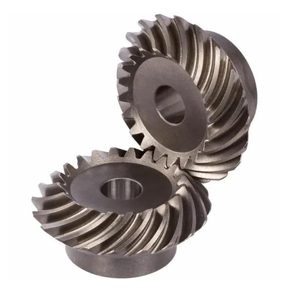
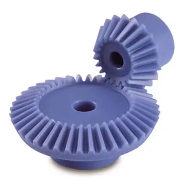
Raydafon manufactures spiral bevel gears for right-angle drives in its own factory in Ningbo, China. The curved tooth line keeps two or more teeth in contact at every moment, so the drive runs more smoothly and quietly than a straight bevel pair of the same size and carries more torque for its dimensions. Standard modules run from M3 to M12 with precision grades DIN6 to DIN9, produced to ISO, DIN, ANSI, JIS or BS. Materials include alloy steel, C45, stainless steel, brass, copper, aluminium and POM, with surface treatments from zinc and nickel plating to black oxide, Geomet and Dacromet. The pinion can be cut with as few as five teeth, allowing a large reduction ratio in a single right-angle stage, and tooth flanks can be ground after heat treatment for the higher precision grades. Gears are supplied as matched pairs with the contact pattern checked before dispatch. Send your drawing or sample for a quotation within 24 hours.

Spiral Bevel Gear — Curved-Tooth Right-Angle Drive, M3 to M12

The spiral bevel gear is the right-angle transmission choice when smoothness and load capacity matter more than anything else. Curved tooth lines keep two or more teeth in contact at every moment, so the drive runs quietly, wears evenly and carries far more load than a straight bevel pair of the same size. Raydafon cuts, heat treats and grinds these gears in its own factory in Ningbo, China.

5 teeth minimumOn the pinion, allowing large single-stage ratios
DIN6 – DIN9Precision grades, ground on request
M3 – M12Standard modules, others to drawing

Design Rationale

Why Choose a Spiral Bevel Gear Instead of a Straight Bevel Gear

The difference between the two is entirely in the tooth line. A straight bevel gear's teeth run radially, so each tooth engages the mating tooth across its full width at the same instant — a sudden impact that repeats at every tooth. A spiral bevel gear's teeth are cut on a curve, so contact begins at one end of the tooth and sweeps across to the other, exactly the way a zip closes. That single geometric change is responsible for every advantage below.

Spiral bevel gear

  • Two or more teeth share the load at all times, because the overlap coefficient is higher
  • Gradual engagement instead of impact, so running noise is substantially lower
  • Contact pressure spread across a longer contact line, giving more uniform wear
  • Pinion can run with as few as 5 teeth, allowing a large ratio in a single stage
  • Contact pattern adjustable through cutter head radius, and can be improved further by grinding
  • Produces an axial force that the shaft bearings must be selected to carry

Straight bevel gear

  • One tooth carries the full load at the moment of engagement
  • Impact at each tooth entry produces more noise and vibration
  • Higher local contact pressure, so wear tends to concentrate
  • Practical minimum tooth count on the pinion is higher, limiting single-stage ratio
  • Simpler and cheaper to cut, which suits low-speed, low-noise-critical drives
  • No axial force generated, so bearing selection is simpler

One design point worth planning for: because the tooth line is helical, a spiral bevel gear generates axial thrust along the shaft. That is not a defect — it is the price of smooth engagement. The bearings must be chosen to take it, which is why a spiral bevel pair is normally specified together with the shaft and bearing arrangement rather than as a drop-in replacement for a straight bevel pair.

Specifications

Spiral Bevel Gear Specifications and Available Options

  • Model number (module)M3, M4, M5, M8, M12 and others
  • Tooth formSpiral (curved tooth line), right-angle drive
  • Minimum pinion tooth count5 teeth
  • Precision gradesDIN6, DIN7, DIN8, DIN9
  • StandardsISO, DIN, ANSI, JIS, BS and non-standard / to drawing
  • MaterialsAlloy steel, C45 steel, stainless steel, brass, copper, aluminium, POM
  • Tooth processingMilled, hardened, or ground (grinding used for the higher precision grades)
  • Tolerance0.001 mm – 0.1 mm depending on feature and precision grade
  • Surface treatmentZinc-plated, nickel-plated, passivation, oxidation, anodization, Geomet, Dacromet, black oxide, phosphatizing, powder coating, electrophoresis
  • Additional operationsShot blasting, sandblasting, heat treatment, annealing, tempering, polishing
  • PackingPlastic bag and carton, or wooden case
  • Payment termsT/T, L/C
  • Production lead time20 business days for samples, 25 days for bulk
  • SamplesSample price USD 2–100; sample express freight paid by the customer

Full specification sheet. Scroll the table sideways on a mobile device to read every row.

Item Specification
Model number M3, M4, M5, M8, M12, etc.
Material Brass, C45 steel, stainless steel, copper, POM, aluminium, alloy, and others
Standard ISO, DIN, ANSI, JIS, BS and non-standard
Precision DIN6, DIN7, DIN8, DIN9
Teeth treatment Hardened, milled or ground
Tolerance 0.001 mm – 0.01 mm – 0.1 mm, depending on the feature and the precision grade specified
Surface treatment Zinc-plated, nickel-plated, passivation, oxidation, anodization, Geomet, Dacromet, black oxide, phosphatizing, powder coating, electrophoresis
Finish Shot blasting, sandblasting, heat treatment, annealing, tempering, polishing
Items packing Plastic bag and carton, or wooden packing
Payment terms T/T, L/C
Production lead time 20 business days for the sample, 25 days for bulk
Samples Sample price range USD 2–100. Sample express freight paid by the customer.
Application Automatic controlling machines, semiconductor industry, general industrial machinery, medical equipment, solar energy equipment, machine tools, parking systems, high-speed rail and aviation transport equipment, and similar

About tolerance and precision: the figures in this table are a range across the whole product family, not a single guaranteed value. Tolerance depends on the feature being measured, the module and the precision grade you specify — a DIN6 ground gear holds much tighter limits than a DIN9 milled one. Tell us the backlash and contact-pattern requirement of your assembly and we will confirm what grade and process your gear needs.

Manufacturing

How We Manufacture and Control Spiral Bevel Gear Quality

Spiral bevel gears are among the hardest gear types to produce well, because the tooth flank is a curved surface that has to be generated, not simply cut. The process we run on every order is deliberately sequential: each step is finished and inspected before the next begins, so a problem is caught at the stage that created it rather than at final assembly.

Blank preparation

Material is selected to the drawing and the blank is turned and faced to establish the mounting faces and bore that every later operation references.

Gear cutting

Tooth flanks are generated on a spiral bevel gear cutting machine using the cutter head radius that produces the required spiral angle and contact pattern.

Heat treatment

Case hardening raises tooth-surface hardness for wear resistance while the core stays tough enough to absorb the impact loads the drive will see.

Tooth grinding

Where a higher precision grade is specified, the flank is ground after heat treatment to correct distortion and improve the contact area and surface finish.

Contact pattern check

The pair is run in a test rig with marking compound so the contact pattern position, shape and size can be inspected against the drawing before the pair is released.

Inspection and packing

Final dimensional check on the features that matter to the assembly, then protective packing for export — plastic bag and carton, or a wooden case for larger sets.

Spiral bevel gear with curved tooth flanks produced by Raydafon
Spiral bevel gear with generated curved tooth flanks.
Spiral bevel gear pair showing matched contact pattern and mounting faces
Matched gear pair — contact pattern and mounting faces.
Spiral bevel gear tooth flank detail after grinding
Tooth flank detail after grinding.
Spiral bevel gear inspection and measurement before packing
Final dimensional inspection before packing.
Spiral bevel gear set prepared for export packing
Gear set prepared for export packing.

Key Advantages

Product Features

Smooth running and low noise

Because the tooth line is curved, at least two teeth are in mesh at any instant and the load is handed from one tooth to the next as contact sweeps across the flank. There is no single moment of full-width impact as there is with a straight bevel gear, so vibration and noise fall noticeably — which is what makes this tooth form the standard choice where noise is controlled, from machine tool spindles to passenger vehicle axles.

High load capacity and even wear

The helix angle raises the overlap coefficient, which means more teeth share the load and the contact pressure on each flank is lower. Lower pressure combined with a longer contact line spreads wear more evenly across the tooth surface instead of concentrating it near the pitch line. The practical result is a gear that carries heavier torque for its size and holds its accuracy longer under continuous duty.

Wide ratio range in a single stage

The pinion of a spiral bevel pair can be cut with as few as five teeth, which allows a large reduction ratio to be achieved in one right-angle stage rather than two. For a machine designer that means fewer parts, a shorter housing and less accumulated backlash, which is why this tooth form appears so often in compact right-angle gear units.

Contact pattern can be corrected

Because the flank curvature is set by the cutter head radius, the contact pattern can be shifted and corrected at the cutting stage, and improved further by grinding after heat treatment. That control over where the teeth actually touch is what separates a gear set that runs quietly for years from one that whines and pits within months — and it is a capability that depends on the machine and the operator, not on the drawing alone.

Materials and surface treatments to suit the duty

The same tooth geometry can be produced in alloy steel for high-torque drives, C45 or stainless steel where corrosion resistance matters, and brass, copper, aluminium or POM for lighter or non-magnetic applications. Surface treatment is then selected to match the environment — zinc or nickel plating, black oxide, Geomet or Dacromet for corrosion protection, anodization for aluminium, and powder coating or electrophoresis for appearance and added durability.

Applications

Where Spiral Bevel Gears Are Used

Anywhere a drive has to turn through 90 degrees while carrying real torque and staying quiet:

  • Machine tools — spindle drives, indexing heads and feed mechanisms where transmission accuracy sets the finished part quality
  • Automotive and transport — differential and final-drive gearing, where a low-noise, high-load right-angle pair is essential
  • Automatic controlling machines — cam indexers, rotary tables and pick-and-place mechanisms
  • Semiconductor and medical equipment — drives that must be smooth, quiet and repeatable rather than merely strong
  • Solar energy equipment — tracker slewing drives, where the gear set operates in outdoor conditions year round
  • Parking systems and logistics equipment — lift and transfer mechanisms needing compact right-angle reduction
  • High-speed rail and aviation ground equipment — auxiliary drives where reliability and low vibration are specified
  • General industrial machinery — pumps, mixers, conveyors and any compact right-angle gear unit

If your application is not listed, describe the duty — input speed, torque, ratio and mounting arrangement. A spiral bevel pair is normally designed together with its shaft and bearing layout because of the axial thrust it generates, so the earlier we see the arrangement, the better the result.

Customisation

Custom Spiral Bevel Gears Made to Drawing

Beyond the standard module range, the parameters that decide whether a gear fits your housing can all be produced to requirement. Typical customisation includes:

  • Module and tooth count
  • Spiral angle and hand of spiral
  • Ratio and matched pair
  • Bore, keyway and spline
  • Hub and mounting face geometry
  • Material selection
  • Precision grade DIN6–DIN9
  • Surface treatment
  • Ground or milled tooth flank
  • Marking and paired set identification

Send a dimensioned drawing, a sample gear, or the required ratio, torque and envelope and we will confirm the closest standard geometry or quote a new one. Spiral bevel pairs are supplied as matched sets, so if you are replacing one gear of a pair, tell us — replacing only half of a matched pair generally produces noise and rapid wear, even if both parts are dimensionally correct.

Buyer FAQ

Buyer FAQ

  • What is the difference between a spiral bevel gear and a straight bevel gear?The tooth line: straight bevel teeth run radially and engage across their full width at once, while spiral bevel teeth are curved so contact sweeps gradually from one end of the tooth to the other. The curved form gives higher overlap, so load is shared by more teeth, running is smoother and quieter, wear is more even, and the pinion can be cut with as few as 5 teeth.
  • Can you make a spiral bevel gear to my drawing or from a sample?Yes. Send a dimensioned drawing or the sample gear with module, tooth count, spiral angle, ratio, bore and material. We confirm whether the geometry matches existing tooling or requires a new cutter setup, quote accordingly, and can supply a sample in about 20 business days.
  • What materials and surface treatments are available?Alloy steel and C45 for high-torque drives, stainless steel where corrosion resistance is needed, and brass, copper, aluminium or POM for lighter or non-magnetic applications. Surface treatments include zinc and nickel plating, passivation, oxidation, anodization, Geomet, Dacromet, black oxide, phosphatizing, powder coating and electrophoresis. Tell us the environment and we will recommend one.
  • Should I order a matched pair or a single gear?Order a matched pair. Spiral bevel gears are lapped and their contact pattern checked as a set, so replacing only one gear of an existing pair usually produces noise and accelerated wear even when both parts measure correctly. If only one gear is damaged, send us both so the replacement can be matched to the surviving part.
  • Why does a spiral bevel gear need special bearings?Because of the helix angle in the tooth line, the gear generates an axial thrust force along the shaft in addition to the tangential and radial loads. The bearings must be selected to carry that thrust — commonly a tapered roller or angular contact arrangement — which is why a spiral bevel pair is best specified together with the shaft and bearing layout.
  • What are your tolerance, lead time and payment terms?Tolerance depends on the feature and the precision grade, ranging from 0.001 mm to 0.1 mm across the family; tell us your backlash and contact-pattern requirement and we will confirm what grade achieves it. Samples take about 20 business days and bulk production 25 days, sample prices are USD 2–100 with express freight paid by the customer, and payment terms are T/T or L/C.

Related

Related Products and Further Reading

Request a Spiral Bevel Gear Quotation

Send your drawing, sample, or the required module, ratio, torque and envelope. We confirm the geometry, precision grade and material, and reply with price and lead time within 24 hours.

Send Inquiry Now

* Tolerance, lead time and price figures are given as a range across the product family and are confirmed per order against the drawing. Spiral bevel gears are supplied as matched pairs; please confirm the mating part number before ordering.

Send Inquiry
Contact Info
For inquiries about hydraulic cylinders, gearboxes, PTO shafts or price list, please leave your email to us and we will be in touch within 24 hours.
X
We use cookies to offer you a better browsing experience, analyze site traffic and personalize content. By using this site, you agree to our use of cookies. Privacy Policy
RejectAccept