QR Code

Products
Contact Us


Fax
+86-574-87168065

E-mail

Address
Luotuo Industrial Area, Zhenhai District, Ningbo City, China


On a construction site, a massive hydraulic crane lifts a 20-ton steel beam to the top of a high-rise building. In a warehouse, a forklift raises a pallet of goods to the third rack level. In a shipyard, a sync lift system raises an entire vessel for maintenance. These seemingly different operations share one common element: they all rely on the hydraulic lift cylinder to convert fluid power into linear motion. The Hydraulic Lift Cylinder is not merely a component; it is the mechanical muscle that transforms hydraulic pressure into the controlled force needed to lift, lower, and position loads. Without it, modern lifting equipment as we know it would not exist.
So why is the Hydraulic Lift Cylinder considered the backbone of lifting equipment? The answer lies in its unique combination of force density, precision control, and reliability. A hydraulic cylinder can generate enormous force from a relatively small package, far exceeding what an electric actuator or pneumatic system can achieve at the same size. It can be controlled with millimeter precision, allowing for smooth acceleration and deceleration. And it can be designed to withstand the most demanding environments, from arctic cold to desert heat, from corrosive marine atmospheres to explosive industrial zones. This article will examine the engineering principles, technical specifications, and application requirements that make the Hydraulic Lift Cylinder indispensable in lifting equipment. At Raydafon Technology Group Co.,Limited, our factory has been manufacturing Hydraulic Lift Cylinders for over two decades, and we have refined our designs to deliver the performance and reliability that our customers demand.
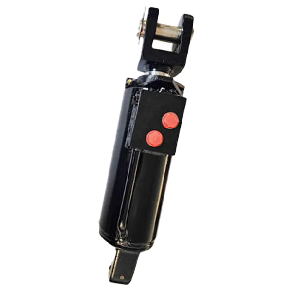
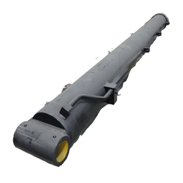
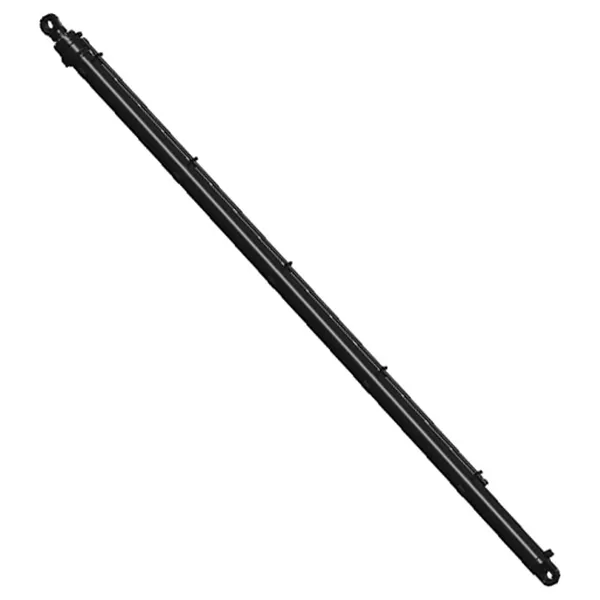
A Hydraulic Lift Cylinder is a mechanical actuator that converts hydraulic pressure into linear force and motion. It consists of a cylindrical barrel, a piston, a piston rod, and sealing elements. Hydraulic fluid is pumped into the cylinder under pressure, pushing against the piston and causing the rod to extend. When the fluid is released, the rod retracts, either under the weight of the load or by a return spring. The force generated by the cylinder is determined by the hydraulic pressure and the effective area of the piston. The relationship is expressed by the formula F = P × A, where F is the force, P is the pressure, and A is the piston area. This simple relationship is the foundation of all hydraulic lifting systems.
To understand the practical implications of this formula, consider a Hydraulic Lift Cylinder with a piston diameter of 100mm. The effective area is approximately 7,854 mm². At an operating pressure of 200 bar (20 N/mm²), the cylinder generates a force of 157,080 N, or approximately 16 tons. This force is generated by a cylinder that weighs only a fraction of the load it can lift. This extraordinary force density is the primary reason why hydraulic systems are preferred for lifting applications. No other linear actuator technology—electric, pneumatic, or mechanical—can match the force-to-size ratio of a Hydraulic Lift Cylinder.
The construction of a Hydraulic Lift Cylinder is designed to withstand the immense internal pressures required to generate these forces. The barrel is typically made from seamless steel tube, honed to a precise internal diameter and surface finish. The piston rod is made from high-strength steel, often chrome-plated to resist corrosion and wear. The seals are made from polyurethane or nitrile rubber, selected for their compatibility with the hydraulic fluid and their resistance to high temperatures. The end caps are threaded or welded to the barrel and feature ports for the hydraulic fluid. At Raydafon, our factory manufactures Hydraulic Lift Cylinders with barrel diameters from 40mm to 500mm, capable of generating forces from 5 tons to over 500 tons. The table below summarizes the key components and their functions.
| Component | Material | Function |
| Barrel | Seamless steel tube, honed | Contains the hydraulic fluid and guides the piston |
| Piston Rod | High-strength steel, chrome-plated | Transmits the force to the load |
| Piston | Steel or aluminum alloy | Separates the pressure chambers and transmits force to the rod |
| Seals | Polyurethane, nitrile rubber, PTFE | Prevent fluid leakage and contamination |
| End Caps | Steel, threaded or welded | Close the cylinder and provide mounting and port connections |
| Bushings | Bronze or composite | Guide the piston rod and absorb side loads |
The choice of materials and the precision of the manufacturing process determine the performance and durability of the Hydraulic Lift Cylinder. A cylinder with a poorly honed barrel will leak internally, reducing efficiency and generating heat. A cylinder with an inadequately chrome-plated rod will corrode, damaging the seals and causing external leaks. At our factory, we adhere to strict tolerances and use only high-quality materials to ensure that our Hydraulic Lift Cylinders deliver reliable performance over their entire service life.
Force density is the amount of force a device can generate per unit of its own weight or volume. It is the single most important factor in the design of lifting equipment. A crane that is too heavy cannot lift its intended load because it must first lift itself. A forklift that is too bulky cannot maneuver in tight warehouse aisles. A hydraulic lift system that is too large cannot be integrated into the equipment. The Hydraulic Lift Cylinder offers the highest force density of any linear actuator technology, making it the only practical choice for heavy lifting applications.
To appreciate the advantage of hydraulic force density, compare a Hydraulic Lift Cylinder to an electric linear actuator. A typical electric actuator with a 100mm stroke and a 10 kN (1 ton) force rating weighs approximately 15-20 kg. A Hydraulic Lift Cylinder with the same stroke and force rating weighs approximately 5-8 kg. The hydraulic cylinder is two to three times lighter for the same force. When the force requirement increases to 100 kN (10 tons), the electric actuator becomes impractically large and heavy, while the hydraulic cylinder remains compact. This is why electric actuators are limited to light-duty applications, while hydraulic cylinders dominate heavy lifting.
The force density of a Hydraulic Lift Cylinder can be further increased by increasing the operating pressure. Modern hydraulic systems operate at pressures up to 350 bar, and some specialized systems operate at 700 bar. At 700 bar, a cylinder with a 100mm piston generates a force of 550 kN (55 tons), yet the cylinder itself weighs less than 50 kg. This extraordinary force density enables the design of compact, powerful lifting equipment that can be transported and operated in space-constrained environments. The table below compares the force density of different actuator technologies.
| Actuator Type | Force (kN) | Actuator Weight (kg) | Force Density (kN/kg) | Typical Application |
| Electric Linear Actuator | 10 | 18 | 0.56 | Light automation, medical beds |
| Pneumatic Cylinder (10 bar) | 8 | 4 | 2.0 | Packaging, assembly |
| Hydraulic Cylinder (200 bar) | 157 | 12 | 13.1 | Forklifts, cranes, excavators |
| Hydraulic Cylinder (350 bar) | 275 | 15 | 18.3 | Heavy lifting, mining equipment |
| Hydraulic Cylinder (700 bar) | 550 | 25 | 22.0 | Specialized lifting, rescue tools |
At Raydafon Technology Group Co.,Limited, we design our Hydraulic Lift Cylinders to maximize force density without compromising safety or durability. We use high-strength steels and advanced sealing technologies to ensure that our cylinders can operate at pressures up to 700 bar. Our factory also offers custom designs for applications that require an optimal balance of force, size, and weight. The force density of the Hydraulic Lift Cylinder is the reason it is the backbone of lifting equipment.
Generating force is only half the story. A Hydraulic Lift Cylinder must also control that force with precision. In lifting equipment, uncontrolled motion can be catastrophic. A crane that lowers its load too quickly can cause the load to swing, potentially striking workers or structures. A forklift that raises its forks too abruptly can destabilize the load, causing it to fall. A lift platform that does not stop at the correct height can cause injury to personnel. The precision control of the Hydraulic Lift Cylinder is therefore as important as its force-generating capability.
Precision control in a Hydraulic Lift Cylinder is achieved through a combination of hydraulic circuit design, valve technology, and cylinder design. The hydraulic circuit controls the flow of fluid to and from the cylinder. Proportional valves and servo valves allow for smooth, infinitely variable control of the cylinder speed. The cylinder design—including the cushioning at the end of the stroke—prevents shock loads when the cylinder reaches its limit. The rod surface finish and the seal design minimize stick-slip, ensuring smooth motion even at very low speeds. The table below outlines the key elements of precision control in a Hydraulic Lift Cylinder.
| Element | Function | Impact on Lifting Performance |
| Proportional Valve | Controls flow rate | Allows smooth, adjustable speed |
| Servo Valve | High-precision flow and pressure control | Enables exact positioning and force control |
| Cushioning | Decelerates the piston at end of stroke | Prevents shock loads and noise |
| Rod Surface Finish | Reduces friction and wear | Minimizes stick-slip at low speeds |
| Seal Design | Maintains a leak-tight seal with low friction | Ensures consistent motion and long life |
The precision control of a Hydraulic Lift Cylinder is particularly critical in applications such as aerial work platforms, where the platform must be positioned exactly at the desired height and held there without drift. It is also critical in synchronized lifting systems, where multiple cylinders must move in perfect unison to lift a large, unbalanced load. At Raydafon, our factory designs Hydraulic Lift Cylinders with precision-machined components and advanced sealing systems to deliver the control performance that these applications demand. We also work closely with our customers to optimize the hydraulic circuit and valve selection for their specific lifting equipment.
The performance of a Hydraulic Lift Cylinder is defined by a set of key technical specifications. These specifications allow engineers to select the right cylinder for their application and to predict its performance. The most important specifications are bore diameter, rod diameter, stroke length, operating pressure, and mounting type. These parameters determine the force, speed, and envelope of the cylinder. At Raydafon Technology Group Co.,Limited, we manufacture Hydraulic Lift Cylinders across a wide range of specifications, and we can customize any parameter to meet specific application requirements.
The table below provides a summary of the standard specifications for our Hydraulic Lift Cylinder product line.
| Specification | Standard Range | Notes |
| Bore Diameter (mm) | 40 - 500 | Larger bore = more force |
| Rod Diameter (mm) | 20 - 360 | Larger rod = more buckling resistance |
| Stroke Length (mm) | 100 - 6000 | Custom strokes available |
| Max Operating Pressure (bar) | 200 - 700 | Higher pressure = more force from same size |
| Max Force (kN) | 50 - 5000 | Depends on bore and pressure |
| Mounting Type | Clevis, flange, trunnion, threaded | Selected based on application |
| Seal Material | Polyurethane, nitrile, PTFE | Selected for fluid compatibility and temperature |
| Rod Surface Finish | Chrome plating, Ra < 0.2 µm | Corrosion resistance and low friction |
| Operating Temperature | -40°C to +120°C | Higher temperatures with special seals |
| Fluid Compatibility | Mineral oil, synthetic, water-glycol | Selected based on application |
In addition to these standard specifications, our factory offers a range of options and accessories for our Hydraulic Lift Cylinders. These include integrated load-holding valves, position sensors, and rod end bearings. We also provide custom coatings and materials for extreme environments, such as marine or offshore applications. Every Hydraulic Lift Cylinder we produce is tested to verify its performance and integrity. We conduct static pressure tests, dynamic cycle tests, and leak tests to ensure that the cylinder meets the required standards. Our commitment to quality and precision is what makes our Hydraulic Lift Cylinders the backbone of lifting equipment around the world.
Selecting the right Hydraulic Lift Cylinder for a specific lifting application is not simply a matter of choosing the largest or most powerful model. It requires a careful analysis of the application's requirements, including the load, the motion profile, the environment, and the available space. The selection process involves a series of engineering calculations and design decisions. The following are the key factors that must be considered.
Load Analysis: The first step is to determine the maximum load that the cylinder must lift. This includes the weight of the payload, the weight of the lifting structure, and any dynamic forces caused by acceleration or shock. A safety factor is then applied to account for uncertainties and overload conditions. The required force determines the bore diameter and the operating pressure.
Motion Profile: The motion profile defines how the load must move. Does it need to move quickly or slowly? Does it need to stop at precise positions? Does it need to hold its position under load? The answers to these questions determine the required flow rate, the valve type, and the need for load-holding devices.
Environmental Conditions: The environment in which the cylinder operates affects the choice of materials and seals. A cylinder operating in a corrosive environment requires stainless steel or special coatings. A cylinder operating in extreme temperatures requires special seals and fluids. A cylinder operating in a dusty environment requires wipers and protective boots.
Space Constraints: The available space determines the mounting type and the overall dimensions of the cylinder. In some applications, a compact cylinder with a short stroke is required. In others, a long-stroke cylinder with a large bore is needed. The mounting type must be compatible with the structure to which the cylinder is attached.
The table below summarizes the key selection criteria for a Hydraulic Lift Cylinder.
| Selection Factor | Considerations | Impact on Cylinder Specification |
| Load | Payload, structure weight, dynamic forces | Determines bore diameter and pressure |
| Motion Profile | Speed, precision, holding requirements | Determines valve type and load-holding devices |
| Environment | Corrosion, temperature, dust | Determines materials and seals |
| Space | Available envelope, mounting constraints | Determines mounting type and overall dimensions |
| Cycle Life | Number of cycles expected | Determines bearing and seal selection |
At Raydafon, our engineering team works closely with customers to select the optimal Hydraulic Lift Cylinder for their application. We provide detailed technical support, including force calculations, motion analysis, and material selection. Our factory also offers custom designs for applications that require a non-standard solution. By combining our engineering expertise with our manufacturing capabilities, we ensure that every Hydraulic Lift Cylinder we deliver meets the specific needs of the lifting equipment it will power.
Question 1: What is the typical lifespan of a Hydraulic Lift Cylinder?
Answer: The lifespan of a Hydraulic Lift Cylinder depends on the operating conditions and maintenance. Under normal conditions, with proper maintenance, a high-quality Hydraulic Lift Cylinder can last 10-15 years or more. The primary wear items are the seals, which can be replaced during a routine overhaul. At Raydafon Technology Group Co.,Limited, we design our cylinders for a minimum of 1 million cycles, and we provide maintenance guidelines to help our customers maximize the service life of their cylinders.
Question 2: How do I know if my Hydraulic Lift Cylinder needs to be replaced or repaired?
Answer: The signs that a Hydraulic Lift Cylinder needs attention include external leaks, a loss of lifting force, unusual noise during operation, and drifting under load. In many cases, the cylinder can be repaired by replacing the seals. If the barrel or rod is damaged, the cylinder may need to be replaced. Our factory offers a repair and overhaul service for Hydraulic Lift Cylinders, and we can advise on whether repair or replacement is the more cost-effective option.
Question 3: What is the difference between a single-acting and a double-acting Hydraulic Lift Cylinder?
Answer: A single-acting Hydraulic Lift Cylinder uses hydraulic pressure to extend the rod, and relies on gravity or a return spring to retract it. A double-acting cylinder uses hydraulic pressure to both extend and retract the rod. Single-acting cylinders are simpler and less expensive, and are used in applications where the load can retract the cylinder. Double-acting cylinders are used in applications where controlled retraction is required, or where the load does not provide enough force to retract the cylinder.
Question 4: Can a Hydraulic Lift Cylinder be used in a vertical position?
Answer: Yes, a Hydraulic Lift Cylinder can be used in any orientation, including vertical, horizontal, or inclined. The design of the cylinder, including the bearing and seal arrangement, is adapted to the orientation. In a vertical application, the weight of the rod and the load must be considered in the design of the hydraulic circuit and the load-holding devices. Our engineering team can provide specific recommendations for vertical applications.
Question 5: What maintenance is required for a Hydraulic Lift Cylinder?
Answer: The maintenance requirements for a Hydraulic Lift Cylinder include regular inspection for leaks, checking the hydraulic fluid level and condition, and replacing the seals at the recommended interval. The rod should be kept clean and free of debris. The hydraulic fluid should be filtered and tested periodically. Our factory provides a detailed maintenance manual with each Hydraulic Lift Cylinder, and we offer maintenance training for our customers.
The Hydraulic Lift Cylinder is the backbone of lifting equipment because it delivers the force density, precision control, and reliability that no other technology can match. From the largest construction crane to the smallest scissor lift, the Hydraulic Lift Cylinder is the component that transforms hydraulic power into the controlled motion that lifts, positions, and holds loads. Its ability to generate enormous force from a compact package, to control that force with millimeter precision, and to operate reliably in the most demanding environments makes it indispensable in modern industry.
At Raydafon Technology Group Co.,Limited, our factory has been manufacturing Hydraulic Lift Cylinders for over two decades. We have the engineering expertise, the manufacturing capability, and the quality systems to deliver cylinders that meet the most demanding requirements. Whether you are designing a new lifting system or maintaining an existing one, we invite you to contact us to discuss your specific needs. Our team is ready to help you select the optimal Hydraulic Lift Cylinder for your application.
Contact Raydafon Technology Group Co.,Limited today to discuss your Hydraulic Lift Cylinder requirements and discover how our cylinders can power your lifting equipment.
+86-574-87168065
Luotuo Industrial Area, Zhenhai District, Ningbo City, China