QR Code

Products
Contact Us


Fax
+86-574-87168065

Email

Address
Luotuo Industrial Area, Zhenhai District, Ningbo City, China



What is a Gear Coupling and how does it work? Picture a massive conveyor line in a mining operation—hundreds of tons of ore moving every hour. Suddenly, a coupling between the motor and the gearbox fails. The entire line stops. Emergency crews scramble, production targets are missed, and the cost per minute of downtime climbs into the thousands. That is the reality when a shaft connection cannot handle the torque or the inevitable misalignment of real-world machinery. A gear coupling is a mechanical device that transmits torque between two shafts through the meshing of internal and external gear teeth, while simultaneously accommodating angular, parallel, and axial misalignment. It works by allowing the crowned teeth on the hubs to slide and rotate within the mating sleeve, distributing loads evenly and preventing binding. Understanding how it works is not just theory—it is the difference between costly unplanned shutdowns and continuous, profitable operation. At Raydafon Technology Group Co.,Limited, we build gear couplings engineered to master these challenges, delivering the torque density and flexibility that procurement professionals trust most.
In this article:
When a procurement team specifies shaft couplings solely based on price, they often overlook a cascade of hidden expenses. A mining dragline sitting idle because a rigid coupling snapped under shock loading loses not just the cost of the replacement part, but also the revenue from hundreds of buckets of overburden that should have been moved. Maintenance crews working overtime, expedited shipping fees, and even safety incidents multiply the true cost of failure. Rigid connections cannot compensate for the thermal expansion of a long shaft train in a paper mill, leading to bearing overload and premature failure. These failures drive up the total cost of ownership and strain maintenance budgets. The solution lies in understanding what a gear coupling does best: it absorbs misalignment while transmitting full-rated torque without imposing excessive radial forces on connected equipment. By selecting a properly sized gear coupling, plants eliminate the root cause of most coupling-related shutdowns. Raydafon Technology Group Co.,Limited works with maintenance teams to analyze these failure patterns and deliver components that turn unplanned downtime into scheduled, predictable maintenance.
At its core, a gear coupling consists of two hubs with external crowned gear teeth, a sleeve—or sleeves—with matching internal teeth, and a lubrication sealing system. As torque flows from one shaft to another, the mated teeth slide relative to each other, pivoting like a human hip joint. This sliding action allows the coupling to accommodate angular misalignment (up to ±1.5° per mesh) and parallel offset without struggle. The crowned tooth profile is the secret: it eliminates edge loading when shafts are not perfectly aligned, spreading the forces over a larger contact area. Think of it as a constant-velocity joint for heavy industry. When you ask “What is a gear coupling and how does it work?”, the answer lies in that dynamic—a balance of sliding, rolling, and hydro-dynamic lubrication that enables the transmission of thousands of horsepower through a compact package. 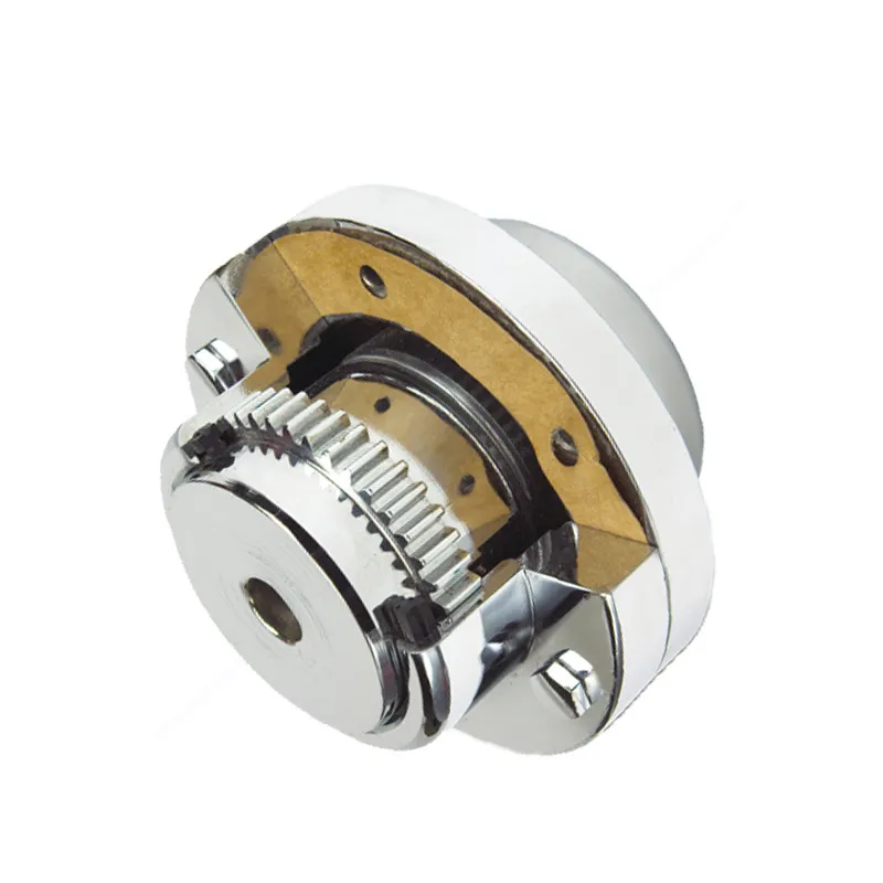
In high-speed applications, such as turbine-driven compressors, precision-manufactured gear couplings from Raydafon Technology Group Co.,Limited maintain an oil film that prevents metal-to-metal contact, ensuring long service life even at 10,000 RPM.
Procurement professionals often face a bewildering array of coupling options. The correct choice hinges on a clear-eyed analysis of operating parameters. Instead of relying on guesswork, successful teams use a data-driven methodology. Start by calculating the peak torque, including service factors for shock, vibration, and duty cycle. Then verify the maximum misalignment angles that the application will impose during operation and thermal growth. Finally, consider the environment—dust, moisture, and temperature extremes can degrade seals and lubricants. A comparison table simplifies the evaluation:
| Parameter | Typical Gear Coupling Range | Key Selection Criterion |
|---|---|---|
| Torque Capacity | 100 – 10,000,000+ Nm | Must exceed peak system torque with service factor |
| Max. Angular Misalignment | ±1.5° per gear mesh | Match to thermal expansion and mounting inaccuracies |
| Speed Capability | Up to 30,000 RPM (balanced) | Requires precision balancing for high-speed applications |
| Lubrication Interval | 500 – 2,000 hours typical | Sealed designs extend intervals; harsh environments demand more frequent lube |
By mapping these values against the manufacturer’s catalog, one quickly narrows down the options. Raydafon Technology Group Co.,Limited provides detailed engineering data on every coupling, making this process transparent and reliable.
When a steel plant’s hot rolling mill faced recurring coupling failures every three months due to extreme heat and scale ingress, they turned to Raydafon. Our engineering team conducted an on-site vibration analysis and redesigned the coupling with high-temperature seals and a proprietary synthetic lubricant. The result: mean time between failures jumped from 90 days to over three years. This outcome stems from a relentless focus on problem-solving: every gear coupling from Raydafon Technology Group Co.,Limited undergoes computerized tooth geometry verification and dynamic balancing to AGMA standards. We use case-hardened alloy steel for hubs and sleeves, achieving surface durability that withstands the pounding of reversing loads. The question “What is a gear coupling and how does it work?” finds its best answer in products that are built to perform in the world’s toughest environments. For procurement managers, this translates to long-term supplier partnerships, reduced inventory variances, and confidence that the next coupling order will deliver the same quality as the last.
Even the best gear coupling will underperform if installed incorrectly. A common pain point is contractors who press-fit hubs without checking the interference, leading to micro-fretting and premature wear. Proper installation involves heating the hub to a calculated temperature for a smooth shrink fit, then verifying hub location with a dial indicator. Once operational, the secret to longevity lies in lubrication. Most failures are traced to lubricant degradation or contamination. Scheduling lubrication top-ups based on operating hours and vibration monitoring can extend life by multiples. For large couplings, using oil with extreme-pressure additives prevents tooth scuffing during startup. Raydafon Technology Group Co.,Limited supplies detailed installation guides and offers commissioning support, helping maintenance teams avoid these pitfalls. The payoff is clear: a well-maintained gear coupling can outlast the machinery it connects.
Q: What is a gear coupling and how does it work in a dusty, abrasive environment like a cement plant?
A: In such conditions, a gear coupling works by keeping the internal gear mesh sealed against dust ingress. Specially designed labyrinth seals and grease-packed chambers create a barrier. The teeth still slide to accommodate misalignment, but the lubricant is fortified with tackifiers to stay in place. Raydafon Technology Group Co.,Limited offers fully enclosed gear couplings with triple-lip seals for cement applications, ensuring that abrasive particles never reach the gear mesh.
Q: What is a gear coupling and how does it work when high torque and severe angular misalignment are both present?
A: When both high torque and high misalignment coexist, a standard coupling may see edge loading. A gear coupling with crowned teeth can handle it because the crowning allows the contact area to shift as misalignment changes, maintaining full face contact. The lubrication film takes the sliding motion, preventing galling. Raydafon’s design uses optimized tooth geometry to increase the allowable misalignment without derating torque, solving a problem that plagues many heavy-duty drive systems.
Have you experienced a coupling failure that disrupted your entire operation? The right choice starts with understanding the real demands of your machinery. Let’s discuss your specific application challenges.
Raydafon Technology Group Co.,Limited, accessible at https://www.transmissions-china.com, is a leading manufacturer of industrial power transmission components, specializing in gear couplings, universal joints, and drive shafts. With decades of engineering expertise, we partner with procurement teams worldwide to deliver reliable, cost-effective solutions that reduce downtime and total cost of ownership. For inquiries, product datasheets, or custom design requests, contact our team at [email protected].
Johnson, K., 2021. Comparative study of gear coupling vs. grid coupling in shock-loaded mill drives. International Journal of Rotating Machinery, 2021, pp. 1-12.
Meier, R. & Deng, S., 2001. Analysis of crowned tooth contact in high-torque gear couplings. Journal of Mechanical Design, 123(4), pp. 578-584.
Li, X. et al., 2018. Lifetime estimation of gear couplings based on lubricant degradation models. Tribology Transactions, 61(5), pp. 845-856.
Patel, H., 1998. Misalignment compensation in double-engagement gear couplings. Gear Technology, 15(2), pp. 22-28.
Rodriguez, A. et al., 2019. Dynamic behavior of gear couplings in high-speed turbomachinery. Proceedings of the ASME Turbo Expo, GT2019-90455.
Chen, L. & Wong, M., 2015. Failure analysis of gear coupling teeth in a continuous casting line. Engineering Failure Analysis, 48, pp. 112-120.
Schmidt, F., 2011. Advances in gear coupling lubrication: from grease to oil mist. Lubrication Engineering, 67(8), pp. 35-41.
O’Brien, T., 2017. The influence of coupling stiffness on rotor dynamics. Sound and Vibration, 51(10), pp. 12-18.
Yamamoto, K. & Tanaka, H., 2005. Development of high-capacity gear couplings for steel mill main drives. ISIJ International, 45(9), pp. 1338-1344.
Davis, M. et al., 2013. Sealing technologies for gear couplings in harsh environments. Sealing Technology, 2013(5), pp. 7-11.
+86-574-87168065
Luotuo Industrial Area, Zhenhai District, Ningbo City, China