QR Code

Products
Contact Us


Fax
+86-574-87168065

E-mail

Address
Luotuo Industrial Area, Zhenhai District, Ningbo City, China


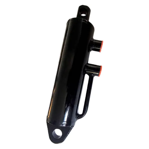
In the world of heavy industry, the Hydraulic Lift Cylinder is the muscle behind some of the most demanding lifting operations. From raising 400-ton ladles of molten steel in a foundry to lifting massive ship hull sections in a shipyard, these cylinders are the components that convert hydraulic pressure into the raw linear force needed to move enormous loads. At the heart of this capability is thrust—the force that the cylinder exerts along its axis. But a Hydraulic Lift Cylinder is not defined by thrust alone. It is a complete system engineered to deliver that thrust reliably, safely, and consistently over thousands of operating cycles. Understanding the design, materials, and construction of a Hydraulic Lift Cylinder is essential for engineers and procurement specialists who need to select the right cylinder for their application.
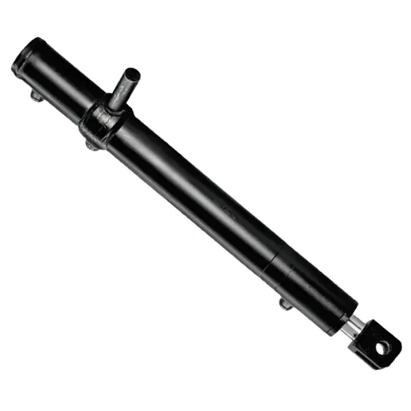
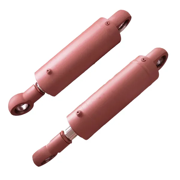
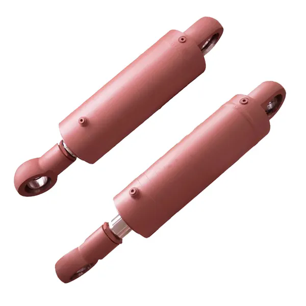
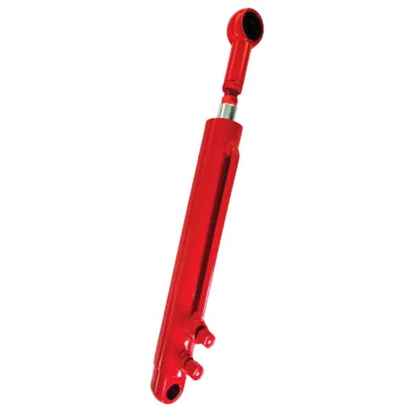
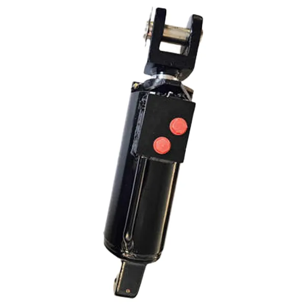
The Hydraulic Lift Cylinder is a device that converts hydraulic pressure into linear force and motion. It consists of a cylinder barrel, a piston, a piston rod, and a sealing system. When hydraulic fluid is pumped into the cylinder, it pushes against the piston, causing the rod to extend or retract. The force generated is determined by the pressure of the fluid and the area of the piston. For large-tonnage applications, this force must be extremely high, and the cylinder must be designed to withstand the resulting stresses without failure. This article will examine the Hydraulic Lift Cylinder in detail, explaining how it generates high thrust, how it resists the forces that would cause it to fail, and how it is engineered to provide reliable service in the most demanding industrial environments. We will also provide detailed specifications and performance data for our Hydraulic Lift Cylinder products from our factory at Raydafon Technology Group Co.,Limited.
Every Hydraulic Lift Cylinder selection begins with a simple question: how much force is needed to move the load? The answer is found in the thrust equation: Thrust = Pressure × Area. This formula is the foundation of cylinder sizing. The pressure is determined by the hydraulic system, typically 200-350 bar for heavy-duty applications. The area is determined by the piston diameter. By rearranging the equation, engineers can calculate the piston diameter required to achieve a specific thrust at a given pressure. For example, if a 200-ton thrust is required at 300 bar, the required piston area is 200,000 kg / 300 bar = 667 cm². The corresponding piston diameter is approximately 291mm. The nearest standard size would be 320mm, which provides a thrust of 246 tons at 300 bar—a comfortable safety margin.
The thrust equation is simple, but its implications are profound. It shows that thrust is proportional to the square of the piston diameter. Doubling the diameter quadruples the thrust. This is why large-tonnage Hydraulic Lift Cylinders are so massive. It also shows that thrust is proportional to pressure. Increasing the pressure allows more thrust from a smaller cylinder, but it requires stronger materials, better seals, and a more robust design. The table below provides a quick reference for cylinder sizing, showing the thrust available from different piston diameters at different pressures.
| Piston Diameter (mm) | Area (cm²) | Thrust at 200 bar (tons) | Thrust at 300 bar (tons) | Thrust at 350 bar (tons) |
| 150 | 176.7 | 36 | 54 | 63 |
| 200 | 314.2 | 64 | 96 | 112 |
| 320 | 804.2 | 164 | 246 | 287 |
| 400 | 1,256.6 | 256 | 384 | 448 |
| 500 | 1,963.5 | 400 | 600 | 700 |
| 630 | 3,117.2 | 635 | 952 | 1,111 |
At Raydafon, our factory manufactures Hydraulic Lift Cylinders with piston diameters up to 1,000mm and operating pressures up to 500 bar. We provide our customers with detailed thrust calculations for their specific applications, taking into account the efficiency of the cylinder and the dynamic forces of the load. This ensures that the cylinder we supply has sufficient thrust to perform the required task safely and reliably.
The cylinder barrel is the pressure vessel of the Hydraulic Lift Cylinder. It is a seamless steel tube that must contain the hydraulic fluid at high pressure without deforming or bursting. The material of the barrel, its wall thickness, and its manufacturing process determine its strength. The most common material for high-pressure cylinders is seamless steel tube made from alloys such as ST52, E355, or 27SiMn. These materials offer a combination of high tensile strength, good weldability, and resistance to fatigue. For extreme applications, such as those found in offshore or mining environments, stainless steel or specialized alloys may be used to provide additional corrosion resistance.
The wall thickness of the barrel is calculated based on the maximum operating pressure, the diameter, and the material's yield strength. The formula for a thick-walled cylinder is more complex than the simple hoop stress formula used for thin-walled vessels. Engineers use the Lamé equations to calculate the stresses in the barrel wall. The barrel is typically manufactured by honing or skiving and roller burnishing to achieve a precise internal diameter and a smooth surface finish. The surface finish is critical because it affects the performance and life of the piston seals. A rough surface will cause the seals to wear quickly, leading to leaks and premature failure. The table below summarizes the key material properties and manufacturing tolerances for our Hydraulic Lift Cylinder barrels.
| Property | Specification | Importance |
| Material | ST52, E355, 27SiMn, or equivalent | High tensile strength for pressure containment |
| Tensile Strength | 500 - 700 MPa | Resists hoop stress and fatigue |
| Yield Strength | 350 - 500 MPa | Prevents permanent deformation |
| Internal Diameter Tolerance | H8 / H9 | Ensures proper fit with piston and seals |
| Surface Roughness (Ra) | 0.2 - 0.4 µm | Minimizes seal wear and friction |
| Wall Thickness Tolerance | +/- 5% | Ensures uniform stress distribution |
| Straightness | 0.5 mm/m max | Prevents bending and misalignment |
At Raydafon Technology Group Co.,Limited, our factory uses only high-quality seamless steel tube from certified suppliers. Each barrel is inspected for material composition, dimensional accuracy, and surface finish before it enters the production line. We use CNC honing machines to achieve the precise internal diameter and surface finish required for long seal life. After honing, the barrel undergoes a rigorous cleaning process to remove any metal particles or debris that could contaminate the hydraulic fluid. This attention to detail is what ensures that our Hydraulic Lift Cylinders can withstand the pressures of large-tonnage applications.
Buckling is the silent killer of Hydraulic Lift Cylinders. It occurs when the compressive load on the piston rod exceeds its critical buckling load. The rod does not break; it bends sideways and fails catastrophically. Buckling is a stability failure, not a strength failure. It is governed by Euler's formula, which shows that the critical buckling load is proportional to the fourth power of the rod diameter and inversely proportional to the square of the rod length. This means that a small increase in rod diameter can dramatically increase the buckling resistance, while a small increase in stroke length can dramatically decrease it. For example, doubling the rod diameter increases the critical buckling load by a factor of 16. Doubling the stroke length reduces it by a factor of 4.
The practical implications of Euler's formula are significant. A Hydraulic Lift Cylinder with a long stroke and a small rod diameter is highly susceptible to buckling. This is why high-thrust cylinders have rods that are disproportionately large relative to the piston diameter. The rod must be large enough to transmit the thrust without buckling, even at the maximum stroke length. In addition to the diameter, the rod material and the support conditions also matter. A rod made from high-strength steel with a high modulus of elasticity will have a higher buckling resistance than a rod made from a lower-strength material. The way the rod is guided and supported also affects the effective buckling length. The table below illustrates the relationship between rod diameter, stroke length, and critical buckling load for a typical Hydraulic Lift Cylinder.
| Rod Diameter (mm) | Stroke Length (mm) | Critical Buckling Load (tons) | Maximum Thrust for Safety Factor of 2 (tons) |
| 100 | 1,000 | 350 | 175 |
| 100 | 2,000 | 87 | 43 |
| 150 | 1,000 | 1,770 | 885 |
| 150 | 2,000 | 442 | 221 |
| 200 | 2,000 | 1,400 | 700 |
| 200 | 3,000 | 622 | 311 |
At our factory, we use advanced computer-aided engineering (CAE) software to perform buckling analysis on every Hydraulic Lift Cylinder we design. This allows us to optimize the rod diameter and the support conditions to ensure a safe and reliable design. We also consider the dynamic effects of the load, such as shock loads and vibration, which can reduce the effective buckling load. Our goal is to provide a cylinder that not only meets the thrust requirements but also has an adequate safety margin against buckling.
The sealing system is the most critical component of a Hydraulic Lift Cylinder for preventing leaks. A leak in a large-tonnage cylinder is not just a nuisance; it is a safety hazard and an environmental concern. The seals must contain hydraulic oil at pressures up to 350 bar or more, while withstanding the movement of the piston and rod. They must also resist extrusion, which occurs when the seal material is forced into the clearance gap between the piston and the cylinder wall. The sealing system typically consists of multiple components: the piston seal, the rod seal, the wiper seal, and the guide rings or bearing strips. Each seal has a specific function and is made from a specific material.
The piston seal is the primary seal that prevents hydraulic fluid from leaking across the piston. It is typically a double-acting seal that can withstand pressure from both directions. The rod seal prevents fluid from leaking out of the cylinder along the rod. It is a single-acting seal that is designed to handle the pressure on the rod side of the piston. The wiper seal, also known as a scraper, removes dirt, dust, and other contaminants from the rod as it retracts, preventing them from entering the cylinder. The guide rings or bearing strips support the piston and rod, maintaining proper alignment and preventing metal-to-metal contact. The table below summarizes the sealing system components and their materials.
| Component | Function | Typical Material | Pressure Rating |
| Piston Seal | Prevents fluid leakage across piston | PTFE + NBR energizer | Up to 400 bar |
| Rod Seal | Prevents fluid leakage along rod | Polyurethane or PTFE | Up to 400 bar |
| Wiper Seal | Removes contaminants from rod | Polyurethane | Low pressure |
| Guide Rings | Supports piston and rod | PTFE + bronze | High load capacity |
| Back-up Rings | Prevents seal extrusion | PTFE or POM | High pressure |
At Raydafon, we use only high-quality seals from reputable manufacturers. Our factory has extensive experience in selecting the right seal materials for each application, considering factors such as the hydraulic fluid type, the operating temperature, the pressure, and the speed of movement. We also offer custom seal designs for special applications. Our Hydraulic Lift Cylinders are tested for leakage at the maximum operating pressure before they are shipped, ensuring that they meet the highest standards of quality and reliability.
Even the most well-designed Hydraulic Lift Cylinder can fail if it is subjected to conditions beyond its design limits or if maintenance is neglected. In large-tonnage applications, a failure can be catastrophic, causing injury, death, and massive property damage. Therefore, a Hydraulic Lift Cylinder for large-tonnage equipment must incorporate a range of safety features to prevent accidents. These features include load-holding valves, pilot-operated check valves, pressure relief valves, and mechanical locking devices. Each of these features provides a layer of protection against different failure modes.
A load-holding valve is a critical safety component that prevents the load from falling if a hydraulic hose or fitting fails. It is a pilot-operated check valve that allows flow into the cylinder but blocks flow out unless a pilot pressure is applied. This means that if the hydraulic line ruptures, the load will remain in position, held by the valve. A pressure relief valve protects the cylinder from overpressure by opening and releasing fluid if the pressure exceeds a set limit. A mechanical locking device, such as a safety nut or a mechanical lock, provides a positive mechanical stop that prevents the load from falling even if the hydraulic system fails completely. The table below summarizes the safety features and their functions.
| Safety Feature | Function | Failure Mode Addressed |
| Load-Holding Valve | Prevents load from falling if hose fails | Hose rupture, fitting failure |
| Pilot-Operated Check Valve | Blocks reverse flow unless piloted | Loss of pilot pressure |
| Pressure Relief Valve | Releases fluid if pressure exceeds limit | Overpressure, thermal expansion |
| Mechanical Lock | Provides positive mechanical stop | Complete hydraulic system failure |
| Rod End Cushion | Decelerates load at end of stroke | Impact damage, shock loads |
At our factory, we design our Hydraulic Lift Cylinders with safety as the first priority. We integrate load-holding valves and pressure relief valves as standard features on all large-tonnage cylinders. We also offer optional mechanical locking devices for applications where the highest level of safety is required. Our engineering team can help you select the right safety features for your specific application and ensure that your lifting system meets all relevant safety standards and regulations.
Selecting the right Hydraulic Lift Cylinder for a large-tonnage application requires a systematic approach that considers the load, the stroke, the speed, the environment, and the safety requirements. The following framework provides a step-by-step guide to the selection process. The first step is to determine the required thrust. This is calculated from the weight of the load, the friction in the system, and any dynamic forces. A safety factor of 1.5 to 2.0 is typically applied. The second step is to determine the required stroke. This is the distance that the load must be moved. The third step is to determine the operating pressure. This is usually determined by the hydraulic power unit, but it can be optimized for the application. The fourth step is to select the piston diameter and rod diameter that meet the thrust and buckling requirements. The fifth step is to select the mounting type and the safety features.
The table below provides a selection matrix for common large-tonnage applications. It lists the typical thrust, stroke, and pressure requirements, along with the recommended cylinder specifications.
| Application | Thrust Required (tons) | Stroke (mm) | Pressure (bar) | Piston Diameter (mm) | Rod Diameter (mm) | Safety Features |
| Hydraulic Press | 200 - 1,000 | 500 - 1,500 | 250 - 350 | 320 - 630 | 200 - 400 | Pressure relief, load holding |
| Shipyard Lift | 300 - 800 | 2,000 - 6,000 | 200 - 320 | 400 - 630 | 250 - 450 | Load holding, mechanical lock |
| Mining Excavator | 100 - 300 | 1,000 - 3,000 | 300 - 350 | 200 - 400 | 150 - 300 | Load holding, cushioning |
| Steel Mill Equipment | 50 - 400 | 500 - 2,000 | 300 - 400 | 150 - 450 | 100 - 320 | Pressure relief, high-temp seals |
| Offshore Platform | 100 - 500 | 1,500 - 4,000 | 250 - 350 | 200 - 500 | 150 - 360 | Load holding, corrosion resistance |
At Raydafon Technology Group Co.,Limited, we have extensive experience in supplying Hydraulic Lift Cylinders for all these applications. Our factory has the capability to manufacture custom cylinders to meet the specific requirements of each project. We work closely with our customers to understand their application and to provide the optimal cylinder design, materials, and safety features. Our technical team is available to assist with the selection process and to provide detailed engineering support.
Question 1: What is the maximum thrust a Hydraulic Lift Cylinder can generate?
Answer: The maximum thrust depends on the piston diameter and the operating pressure. Our standard cylinders can generate up to 2,000 tons of thrust. However, we can manufacture custom cylinders with even higher thrust capacities if required. The thrust is calculated as Pressure × Area, so increasing either the pressure or the piston area will increase the thrust. The practical limit is determined by the strength of the materials and the size of the cylinder.
Question 2: How do I calculate the required thrust for my Hydraulic Lift Cylinder application?
Answer: To calculate the required thrust, you need to determine the total load that the cylinder must move. This includes the weight of the object, the friction in the system, and any dynamic forces from acceleration or deceleration. Once you have the total load, you can calculate the required pressure using the formula: Pressure = Force / Area. You also need to include a safety factor, typically 1.5 to 2.0, to account for unexpected loads. Our engineering team can assist you with the calculation for your specific application.
Question 3: What is the relationship between thrust and buckling in a Hydraulic Lift Cylinder?
Answer: Thrust and buckling are directly related. The thrust is the compressive force that the cylinder exerts on the rod. If this force exceeds the critical buckling load of the rod, the rod will bend and fail. This is why high-thrust cylinders require larger rod diameters. The critical buckling load increases with the fourth power of the rod diameter, so increasing the rod diameter is a very effective way to increase the buckling resistance. At our factory, we use advanced CAE software to perform buckling analysis on every cylinder design.
Question 4: How often should a Hydraulic Lift Cylinder be inspected?
Answer: The inspection frequency depends on the application and the operating conditions. For critical applications, we recommend a visual inspection daily, a detailed inspection monthly, and a full overhaul every 2-3 years or after a specified number of operating hours. The inspection should include checking for leaks, verifying the rod surface condition, checking the hydraulic fluid for contamination, and testing the safety features. Regular inspection and maintenance are essential for ensuring the safe and reliable operation of the cylinder.
Question 5: Can a Hydraulic Lift Cylinder be repaired, or does it need to be replaced?
Answer: In many cases, a Hydraulic Lift Cylinder can be repaired. The most common repairs are replacing the seals and re-chroming or replacing the rod. If the barrel is damaged or the rod is bent, the repair may be more extensive. At Raydafon Technology Group Co.,Limited, we offer a full repair and reconditioning service for our cylinders. Our factory has the equipment and expertise to restore a cylinder to like-new condition at a fraction of the cost of a new cylinder. We can also provide a replacement cylinder if the repair is not feasible.
High thrust is essential for Hydraulic Lift Cylinders because it is the force that moves the load, the force that must be controlled for safety, and the force that determines the cylinder's ability to perform its function. Without sufficient thrust, a Hydraulic Lift Cylinder is either unable to do its job or is a hazard to the people and equipment around it. The design features that enable high thrust—large piston area, high operating pressure, robust rod design, and advanced sealing systems—are all engineered to work together to deliver the force that large-tonnage applications demand. At Raydafon Technology Group Co.,Limited, our factory has the expertise and the equipment to manufacture Hydraulic Lift Cylinders that meet the most demanding thrust requirements. We use high-quality materials, precision manufacturing processes, and rigorous testing to ensure that every cylinder we produce delivers reliable performance and long service life.
Whether you are designing a new large-tonnage lifting system or upgrading an existing one, we invite you to contact our technical team to discuss your requirements. We can provide detailed product specifications, engineering calculations, and application support. Our commitment to quality and customer satisfaction has made us a trusted partner for industrial hydraulics around the world.
Contact Raydafon Technology Group Co.,Limited today to discuss your Hydraulic Lift Cylinder requirements and discover how our high-thrust cylinders can handle your large-tonnage applications.
+86-574-87168065
Luotuo Industrial Area, Zhenhai District, Ningbo City, China