QR Code

Products
Contact Us


Fax
+86-574-87168065

Email

Address
Luotuo Industrial Area, Zhenhai District, Ningbo City, China


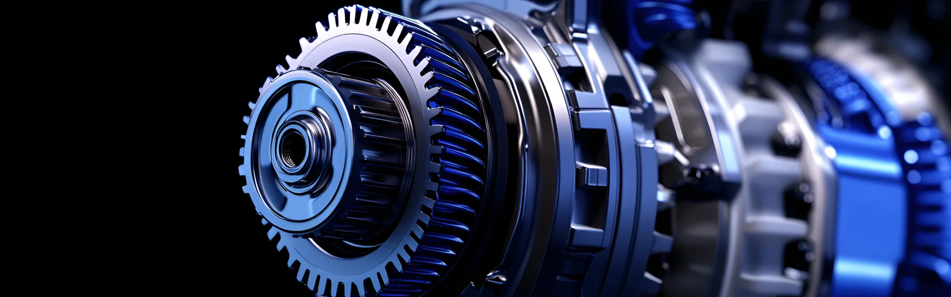
Inside the compact housing of an industrial robotic arm, a servo motor spins at 6,000 revolutions per minute. Yet the output shaft moves with slow, deliberate precision, exerting hundreds of Newton-meters of torque to position a heavy payload. The component that makes this dramatic transformation possible is a Precision Gear: the worm gear. Step inside any manufacturing facility, and you will find worm gears at work in conveyors, lifts, machine tools, and packaging equipment. They are the unsung heroes of mechanical power transmission, converting high-speed, low-torque input into low-speed, high-torque output with a simplicity that other gear types cannot match. But why are worm gears the default choice for high reduction applications? The answer lies in a unique combination of geometry, material science, and physics that other Precision Gear systems simply cannot replicate.
A worm gear pair consists of a threaded worm (the driving element) and a toothed wheel (the driven element). This configuration offers an elegant solution to a fundamental engineering problem: how to achieve large speed reductions in a single stage. A single-start worm with a 60-tooth wheel delivers a 60:1 reduction ratio in a compact package. Achieving the same reduction with spur gears would require a multi-stage arrangement, increasing complexity, cost, and space. Beyond reduction capability, worm gears offer two additional benefits that are critical in many applications: they provide smooth, quiet operation, and they can be designed to be self-locking, preventing reverse motion when power is removed. This article explores the technical foundations of the worm gear's dominance in high reduction applications, from its geometric principles to the material choices that define its performance.
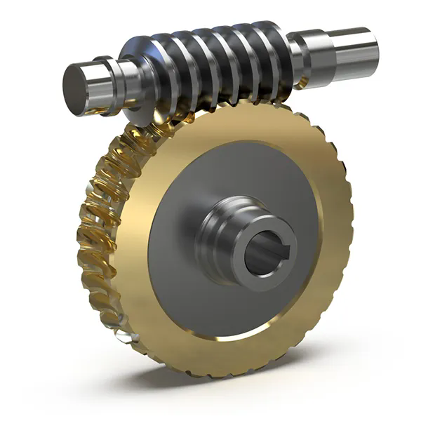
To understand why worm gears excel in high reduction applications, we must first understand their geometry. Imagine a standard bolt. As you turn it, it advances linearly along its threaded shaft. Now imagine wrapping that bolt into a circle, so that its threads become a continuous helix. That is a worm. The wheel that meshes with it is a gear with specially cut teeth that match the worm's thread profile. When the worm rotates, its threads engage the teeth of the wheel, forcing the wheel to rotate. This is the fundamental principle of worm gear operation.
The key to high reduction lies in the relationship between the worm's rotation and the wheel's rotation. For a single-start worm—a worm with a single continuous thread—each full rotation of the worm advances exactly one thread. This thread pushes against one tooth on the wheel, causing the wheel to move by one tooth. If the wheel has 60 teeth, then the worm must rotate 60 times to complete one full rotation of the wheel. The reduction ratio is simply the number of teeth on the wheel. This is a 60:1 reduction achieved in a single gear pair. In contrast, achieving a 60:1 reduction with spur gears would require at least three stages, each with its own shafts, bearings, and housing, significantly increasing the complexity and cost of the transmission.
The geometry becomes even more powerful when considering multi-start worms. A two-start worm has two threads, advancing two teeth per rotation, resulting in a reduction ratio of wheel teeth divided by two. A three-start worm divides the ratio by three. This flexibility allows designers to balance reduction ratio against efficiency. Higher reduction ratios generally mean lower efficiency, as more sliding is required. Multi-start worms offer higher efficiency but lower reduction ratios. This simple geometric relationship—ratio equals tooth count divided by starts—is what makes worm gears such an elegant solution for high reduction applications. With a single stage, you can achieve ratios from 5:1 to over 100:1, a range that is difficult to match with other types of Precision Gear.
Beyond the ratio calculation, the geometry of the worm gear also affects its load-carrying capacity. The worm's thread is a continuous helix, which means that multiple teeth are in contact at any given time. This distributes the load over a larger area, reducing contact stress and allowing the gear to handle higher torques than a comparable spur gear. At our factory, we manufacture worm gears with precisely ground thread profiles to ensure maximum contact and minimal stress concentration. This geometric advantage is why worm gears are the preferred Precision Gear for applications requiring high torque in a compact form factor.
Unlike spur or helical gears, where teeth roll against each other with minimal sliding, the contact between a worm and its wheel is predominantly sliding. Imagine a piece of chalk dragging across a blackboard. The worm's thread slides across the face of each tooth as it rotates, creating friction that generates heat and consumes energy. This sliding action is the primary reason worm gears are less efficient than other gear types. Depending on the reduction ratio and the design parameters, efficiency can range from 50% (for high-ratio, self-locking designs) to over 90% (for low-ratio, multi-start designs).
This is not a design flaw; it is a physical consequence of the geometry. The worm's thread is essentially a screw, and the wheel's teeth are the "nut." In any screw-nut pair, sliding is the fundamental motion. The benefit is that this sliding allows for continuous, smooth engagement, eliminating the impact and noise that can occur with rolling contact gears. In applications where low noise and vibration are essential, such as in precision manufacturing equipment or medical devices, this trade-off is well worth the efficiency loss.
To manage the friction and wear caused by sliding, worm gears rely on a carefully engineered combination of materials and lubrication. The worm is typically made from a hardened steel, such as 42CrMo4 or 20MnCr5, which provides a hard, wear-resistant surface. The wheel is made from a softer material, typically a phosphor bronze (CuSn12 or similar). The bronze acts as a "sacrificial" material, conforming to the worm's thread and reducing wear on the more expensive worm component. The bronze also has excellent bearing properties, reducing the coefficient of friction. The difference in hardness—the worm is typically 58-62 HRC, while the bronze wheel is 80-100 HB—is a deliberate design choice. The softer bronze wears preferentially, protecting the worm and allowing for a long service life.
Lubrication is equally critical. Worm gears require a high-viscosity oil with extreme pressure (EP) additives to maintain a sufficient lubricating film under the high pressures and sliding velocities. Without adequate lubrication, the sliding contact will quickly lead to adhesive wear, scuffing, and premature failure. Our factory recommends specific lubricants for each of our Precision Gear products, based on the load, speed, and operating conditions. We also design our gear housings with adequate oil capacity and cooling fins to dissipate the heat generated by friction.
The following table summarizes the key material and lubrication properties for a typical high-quality Precision Worm Gear.
| Component | Material | Hardness | Lubrication Requirement |
| Worm | 42CrMo4 / 20MnCr5 | 58-62 HRC | High-viscosity EP oil |
| Worm Wheel | CuSn12 (Phosphor Bronze) | 80-100 HB | High-viscosity EP oil |
| Housing | Cast Iron / Aluminum Alloy | N/A | Oil seal for contamination protection |
Understanding this sliding action is essential for anyone selecting a Precision Gear for high reduction applications. The trade-off between efficiency and smooth operation, combined with the proper material and lubrication selection, is what makes a successful worm gear design. Our factory has refined these trade-offs over decades of experience, optimizing our Precision Gear products to deliver reliable, long-lasting performance in the most demanding applications.
Imagine a freight elevator carrying a heavy load. Suddenly, the power fails. The motor stops, and the load begins to descend under gravity, accelerating to a dangerous speed. In a typical gearbox, this would happen. In a properly designed worm gear system, it does not. The load stops and remains suspended, held in place by the friction between the worm and wheel. This is the self-locking feature, a property unique to worm gears that is critical in many high reduction applications.
The self-locking condition arises from the same geometry that gives worm gears their high reduction capacity. The worm is a screw, and the wheel is a nut. When you stop turning the screw, the nut does not back-drive the screw unless the friction is overcome. In a worm gear, self-locking occurs when the friction angle (determined by the coefficient of friction and the pressure angle) exceeds the lead angle of the worm's thread. When this condition is met, the load on the wheel cannot overcome the friction to turn the worm. The system locks, holding the load in place.
The self-locking feature is not automatic. It depends on the reduction ratio and the coefficient of friction. In general, a single-start worm with a reduction ratio of 30:1 or higher will be self-locking under typical operating conditions. Higher friction (from increased load or poorer lubrication) makes self-locking more effective. Conversely, lower friction can reduce or eliminate self-locking. This is why lubricant selection is critical: a lubricant that is too effective at reducing friction can inadvertently defeat the self-locking capability of the gear.
Self-locking is a crucial safety feature in many applications. It eliminates the need for brakes or other holding devices, simplifying the design and reducing cost. It also improves safety by preventing unintended motion during power loss. For example, in a conveyor system, self-locking prevents the belt from reversing when the motor is switched off. In a machine tool, it holds the tool in position during a power outage. This feature is why worm gears are widely used in hoists, lifts, and any application where load-holding is required.
The trade-off is efficiency. Self-locking worm gears are inherently less efficient than non-self-locking designs because friction is required to achieve the locking effect. The same friction that holds the load also robs the system of power during normal operation. In applications where load-holding is not required, a multi-start worm with a lower friction coefficient can be used to improve efficiency.
Our factory engineers can calculate the self-locking condition for any specific design, taking into account the reduction ratio, pressure angle, and expected coefficient of friction. This analysis ensures that our Precision Gear products meet the specific requirements of each application, balancing the need for load-holding with the need for efficiency.
Selecting a Precision Gear for a high reduction application requires a thorough evaluation of technical specifications. These parameters define the gear's performance, longevity, and suitability for a given application. The following table provides an overview of the key specifications for our Precision Worm Gear products. Each parameter is carefully controlled during our manufacturing process to ensure consistent, reliable performance.
| Specification | Value Range | Impact on Performance |
| Center Distance | 20 to 200 mm | Determines the torque capacity and gear size |
| Reduction Ratio | 5:1 to 100:1 | Defines speed reduction and torque multiplication |
| Module | 0.5 to 6 | Affects tooth strength and load capacity |
| Worm Starts | 1 to 6 | Balances efficiency and ratio; single-start for highest ratio |
| Tooth Profile | ZK (K-type) / ZI (I-type) | Grindable profiles for higher precision; ZK is common |
| Gear Precision Grade | DIN 4-6 / AGMA 10-13 | Higher grades ensure smoother operation, lower noise |
| Efficiency | 50% to 92% | Higher efficiency reduces heat and power consumption |
| Maximum Input Speed | 500 to 3000 RPM | Dependent on lubrication and bearing design |
| Maximum Torque | 50 to 5000 Nm | Defines the gear's load-carrying capacity |
| Material Hardness | 58-62 HRC (worm), 80-100 HB (wheel) | Influences wear resistance and service life |
Each specification in this table tells a story about the gear's performance. The center distance determines the gear's size and torque capacity. A larger center distance allows for larger gears, which can handle higher loads. The reduction ratio is the primary parameter defining the gear's function. The module and tooth profile determine the strength and smoothness of the gear's operation. The gear precision grade, typically DIN 4 to 6 for high-quality worm gears, directly affects the noise, vibration, and smoothness of the transmission. Our factory's Precision Gear products are manufactured to DIN 5 or higher, ensuring exceptional performance in demanding applications.
Our factory uses advanced CNC grinding and measurement equipment to achieve and verify these specifications. Our grinding machines can produce tooth profiles with micron-level accuracy, ensuring the correct meshing pattern and load distribution. Our measuring equipment, including gear testers and coordinate measuring machines, verifies that every gear meets the specified tolerances. This attention to detail is what distinguishes a high-quality Precision Gear from a standard one, and it is why our products are trusted in industries where reliability and precision are paramount.
The Precision Worm Gear is a masterclass in engineering trade-offs. Its geometry provides natural, high-speed reduction ratios that are difficult to achieve with other gear types. Its sliding action, while reducing efficiency, enables smooth, quiet operation and allows for a self-locking capability that is critical for safety in many applications. The combination of hardened steel worms and bronze wheels, supported by proper lubrication, yields a durable transmission system that delivers years of reliable service. Whether you are designing a conveyor system, a machine tool, or an agricultural implement, the worm gear offers a solution that is simple, effective, and proven.
At Raydafon, our factory has been manufacturing high-quality Precision Gear products for over 20 years. Our worm gears are engineered to meet the most demanding specifications, with precision grades up to DIN 5. We offer a complete range of sizes and ratios, backed by comprehensive technical support and rigorous quality control. If you are looking for a reliable partner for your Precision Gear needs, we invite you to contact us to discuss your application. Contact Raydafon Technology Group Co.,Limited today to discover how our Precision Worm Gear solutions can power your next project.
Question 1: What is the difference between a single-start and a multi-start worm, and how do I choose between them?
Answer: A single-start worm has one continuous thread, resulting in the highest reduction ratio for a given wheel tooth count. The reduction ratio equals the number of teeth on the wheel. A multi-start worm has two or more threads, reducing the reduction ratio but increasing efficiency. For example, a 60-tooth wheel with a single-start worm gives a 60:1 ratio; with a two-start worm, the ratio is 30:1. Choose a single-start worm when maximum reduction is required and efficiency is less critical. Choose a multi-start worm when you need a moderate reduction with higher efficiency, or when self-locking is not required.
Question 2: Why do worm gears generate so much heat, and how can this be managed?
Answer: The heat in a worm gear is generated by the sliding friction between the worm and the wheel teeth. This is an inherent characteristic of the worm gear geometry. To manage heat, worm gear systems require adequate lubrication to reduce friction and carry away heat. The housing should be designed with sufficient surface area to dissipate heat through convection. In high-power applications, forced cooling (fan cooling or liquid cooling) may be required. Our factory can recommend the appropriate cooling method for your specific application.
Question 3: How can I determine if my worm gear is experiencing excessive wear?
Answer: The most common signs of excessive wear in a worm gear are increased backlash, increased noise, and higher operating temperatures. Visual inspection of the gear teeth can reveal signs of wear, such as a polished or worn appearance, pitting, or scuffing. Regular oil analysis can detect the presence of wear particles, providing an early indication of wear. The most reliable method is to monitor the gear's performance over time and conduct periodic inspections. Our factory recommends a routine inspection schedule based on the operating conditions of the gear.
Question 4: Can a worm gear be driven in reverse by the load?
Answer: This depends on the gear's design. If the gear is self-locking, the load cannot drive the worm in reverse. However, if the friction is insufficient (due to low load, high lubrication, or a multi-start design with a small reduction ratio), the load can back-drive the worm. In many applications, this is undesirable and the self-locking feature is intentionally incorporated. In other applications, back-drivability may be required for safety or operational reasons. Our factory can design a Precision Gear with the appropriate self-locking characteristics for your specific application.
Question 5: What is the typical precision grade for a high-quality worm gear?
Answer: A high-quality Precision Gear is typically manufactured to DIN 5 or AGMA 12 quality standards or better. These grades ensure smooth operation, low noise, and minimal backlash. For less demanding applications, DIN 6-7 may be acceptable. Our factory can manufacture worm gears to DIN 4 grade for the highest precision applications, such as machine tool positioning and robotics. The selection of the precision grade depends on the application's accuracy and noise requirements.
+86-574-87168065
Luotuo Industrial Area, Zhenhai District, Ningbo City, China