QR Code

Products
Contact Us


Fax
+86-574-87168065

Email

Address
Luotuo Industrial Area, Zhenhai District, Ningbo City, China


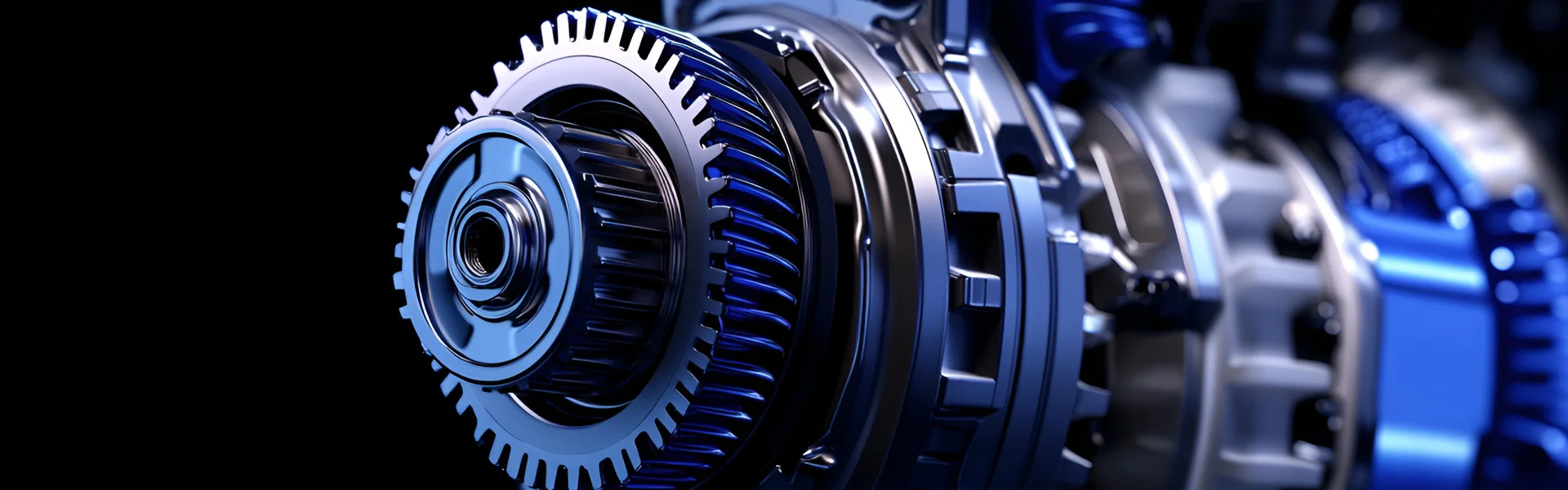
Imagine standing next to a high-speed industrial gearbox operating at 3,000 RPM. If it contains straight-cut spur gears, the sound is a distinct, high-pitched whine—almost a shriek—that can be physically uncomfortable. This noise is not merely an annoyance; it is the audible signature of impact, friction, and vibration that signals energy loss and potential wear. Now imagine the same gearbox fitted with helical precision gears. The sound becomes a smooth, subdued hum—almost a whisper. This dramatic difference is the result of a fundamental geometric distinction between how helical gears and spur gears transmit power. At Raydafon Technology Group Co.,Limited, our factory has been manufacturing Precision Gear products for over two decades, and we have seen how the transition from spur to helical geometry has transformed industries from automotive to aerospace. This article will dissect the engineering principles that enable helical precision gears to reduce noise and vibration, moving beyond simple descriptions to explore the physics of tooth contact, the mathematics of overlap ratios, and the manufacturing precision required to realize these benefits.
The noise and vibration generated by gear pairs are the result of two primary mechanical phenomena: impact excitation at the moment of tooth engagement, and the periodic variation in mesh stiffness as teeth enter and exit contact. Spur gears, with teeth that engage simultaneously across their entire face width, create a sudden, impulsive loading that generates high-frequency vibration and noise. Helical precision gears, by contrast, feature teeth that are cut at an angle to the gear axis. This angle causes the tooth engagement to be progressive—a rolling, sliding contact that begins at one end of the tooth and moves across the face width. This progressive engagement eliminates the "hammering" effect of simultaneous contact, dramatically reducing the impact forces that generate noise. In the following sections, we will examine this phenomenon in detail, quantifying the benefits through key parameters such as contact ratio and transverse overlap, and exploring the advanced manufacturing techniques that ensure these theoretical advantages are realized in practice.
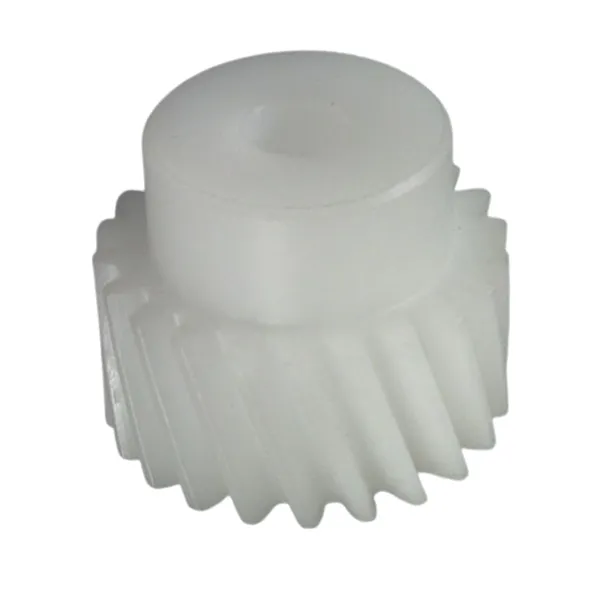
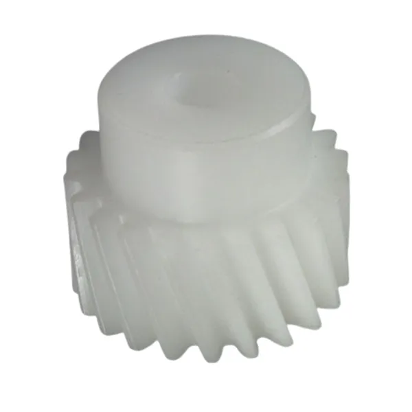
To understand how helical precision gears achieve their superior noise and vibration characteristics, we must first establish a clear picture of what they are and how they differ from other gear types. Imagine a standard spur gear—the teeth are straight and parallel to the gear's axis of rotation. When two spur gears mesh, the teeth engage along a line that extends across the entire face width of both gears simultaneously. This is a "line contact" that occurs abruptly, with the full load being applied in an instant as the tooth pair enters the mesh. Now imagine taking that spur gear and cutting its teeth at an angle to the axis, like the threads on a screw. This is a helical gear. The angled teeth create a completely different engagement dynamic: instead of a full line of contact appearing suddenly, the contact point starts at one end of the tooth and moves progressively across the face width as the gear rotates.
The helix angle—typically ranging from 8° to 30° for most industrial applications—is the defining geometric parameter of a helical gear. This angle introduces a significant engineering advantage: the progressive tooth engagement reduces the rate of load application, minimizing the impact forces that generate noise and vibration. Moreover, the helical gear always has more than one tooth pair in contact at any given moment, which distributes the load over a larger surface area and smooths the overall torque transmission. These benefits are so substantial that helical precision gears have become the default choice for applications where smoothness and quiet operation are paramount—from automotive transmissions and wind turbines to robotics and precision machinery. At Raydafon, our Precision Gear portfolio is dominated by helical designs, with helix angles optimized through extensive testing for each specific application.
However, the helical geometry introduces a complication: the angled teeth generate an axial thrust force that must be managed, typically through the use of thrust bearings or by using double-helical (herringbone) gears. This added complexity is a small price to pay for the dramatic improvements in noise, vibration, and load-carrying capacity. Our factory has developed proprietary bearing designs and housing configurations that effectively manage these thrust loads, ensuring that our helical precision gears deliver their benefits without compromising system reliability. In the next section, we will take a "slow-motion" look at tooth engagement, comparing the impact dynamics of spur and helical gears to understand the origins of their noise signatures.
To appreciate the noise-reducing effect of helical gears, we must first understand the noise-generating mechanism in spur gears. Imagine two spur gears meshing at high speed. As the gears rotate, a pair of teeth approaches engagement. The moment the leading edges make contact, the entire face width of the tooth pair is suddenly loaded. This creates a sharp, impulsive force that propagates through the gear body and into the supporting structure. The impulse excites a broad spectrum of vibration frequencies, many of which fall within the audible range. This is the source of the characteristic "whine" of spur gears—it is, in effect, the sound of metal striking metal, repeated thousands of times per minute. The energy of this impact also contributes to wear, pitting, and fatigue, reducing the service life of the gear pair.
Now picture a helical precision gear pair in slow motion. The tooth engagement begins not with a sudden line contact, but with a point contact at one corner of the tooth. As the gear rotates, this contact point moves diagonally across the face width, tracing a path from the leading edge to the trailing edge. This is a process of "rolling engagement" rather than "impact engagement." The load is applied gradually over the duration of the engagement cycle, rather than instantaneously. This gradual application of load significantly reduces the peak force transmitted to the gear body, which in turn reduces the vibration amplitude and the resulting noise. Our factory has conducted extensive comparative testing, and the results are consistent: a helical precision gear of equivalent size and tooth count typically generates 8-12 dB less noise than a spur gear, which corresponds to a reduction of more than 80% in perceived loudness.
To put this in perspective, consider the following comparison of key engagement parameters for spur and helical gears under similar operating conditions. These values are based on testing conducted at our factory using a standardized test rig and a consistent set of operating parameters (3,600 RPM, 50 N·m torque).
| Parameter | Spur Gear (Straight Teeth) | Helical Precision Gear |
| Contact Type | Instantaneous line contact | Progressive point-to-line contact |
| Load Application Rate | High (impact) | Low (gradual) |
| Peak Vibration Acceleration | 18.2 m/s² | 6.4 m/s² |
| Sound Pressure Level (at 1m) | 88.5 dB(A) | 76.3 dB(A) |
| Dynamic Load Factor | 1.8 | 1.2 |
The dynamic load factor, shown in the table, is a measure of how much the actual load exceeds the nominal load due to impact effects. A factor of 1.8 for spur gears means that the teeth experience nearly twice the force that would be predicted by simple static analysis—a significant contributor to accelerated wear and fatigue. The reduced dynamic load factor of helical gears explains why they not only run quieter but also last longer. At Raydafon, we design our helical Precision Gear products with optimized helix angles to minimize dynamic loads for each specific application. This is not a one-size-fits-all parameter; a helix angle that works well for a low-speed application may be suboptimal for a high-speed one.
The progressive engagement of helical teeth is only half the story. The other, equally important factor is the concept of "overlap ratio" or "contact ratio," which quantifies the average number of tooth pairs in contact at any given moment. In a spur gear, the contact ratio is typically between 1.3 and 1.6. This means that, on average, only one or one-and-a-half tooth pairs are sharing the load at a given time. As a tooth pair exits the mesh and the next pair enters, there is a brief moment when the number of teeth in contact drops, causing a fluctuation in the mesh stiffness. This fluctuation is a primary source of vibration in spur gear systems—the gear "shudder" as load transfers from one tooth pair to the next.
A helical precision gear, by contrast, has a much higher total contact ratio. This is because the total contact ratio is the sum of the transverse contact ratio (the same as a spur gear) and the overlap ratio, which is introduced by the helix angle. The overlap ratio is the axial overlap of tooth pairs along the face width. For a well-designed helical gear, the overlap ratio is typically 1.0 or greater, meaning that the total contact ratio is often in the range of 2.0 to 2.5. This means that there are, on average, two to two-and-a-half tooth pairs in contact at any given moment. The load is distributed across more teeth, and the transition from one pair to the next is smooth because the overlap ensures that the entering pair is already carrying some load before the exiting pair disengages. This overlap eliminates the cyclical variation in mesh stiffness that is a primary source of vibration in spur gears.
To visualize the difference, imagine carrying a heavy object with one hand versus two hands. With one hand, the load is concentrated, and any change in posture is jarring. With two hands, the load is shared, and the transition is smooth. The same principle applies to gear teeth. The higher contact ratio of helical precision gears results in a smoother torque transmission with lower vibration amplitudes. This is particularly important in high-speed applications where even minor torque fluctuations can excite resonances in the supporting structure, leading to noise and potential damage. Our factory has developed a proprietary tooth profile optimization algorithm that maximizes the contact ratio for a given helix angle and face width, ensuring that our Precision Gear products deliver the smoothest possible power transmission.
| Parameter | Spur Gear | Helical Precision Gear |
| Transverse Contact Ratio | 1.4 | 1.4 |
| Overlap Ratio (axial) | 0.0 | 1.1 |
| Total Contact Ratio | 1.4 | 2.5 |
| Number of Teeth in Contact (avg.) | 1.4 | 2.5 |
| Mesh Stiffness Variation | High (25-30%) | Low (5-8%) |
The reduction in mesh stiffness variation, shown in the final row of the table, is a key indicator of vibration potential. The near-constant mesh stiffness of a helical precision gear means that the gear pair acts almost like a solid coupling, transmitting power smoothly and quietly. This is why helical gears are the preferred choice for applications requiring high precision and low noise, such as medical imaging equipment, aerospace actuators, and high-end automotive transmissions. At Raydafon Technology Group Co.,Limited, we pride ourselves on manufacturing Precision Gear products that consistently achieve contact ratios of 2.4 or higher, ensuring our customers benefit from the smoothest possible power transmission.
The theoretical advantages of helical geometry—progressive engagement and high overlap ratio—can only be fully realized if the gears are manufactured with exceptional precision. In fact, manufacturing errors are often the primary source of noise and vibration in gear systems, even when the geometry is theoretically perfect. A helical precision gear with a slight tooth pitch error, a runout in the bore, or a profile deviation will generate vibration regardless of its helix angle. At our factory, we have invested heavily in the latest gear manufacturing and inspection technologies to ensure that every Precision Gear we produce meets the tightest tolerances. This section will explore the critical manufacturing parameters that determine gear noise and vibration performance, and how we control them.
The most critical parameter is tooth profile accuracy. The theoretical involute profile of a gear tooth is a mathematically perfect curve that ensures constant velocity ratio. In reality, every gear has some deviation from the ideal profile, which can be measured using a gear inspection machine. This deviation generates transmission error—the difference between the actual and theoretical output shaft position. Transmission error is the fundamental source of vibration in gear pairs: as the gear rotates, the varying tooth contact causes the output shaft to speed up and slow down slightly, generating acceleration forces that excite vibration. Our factory uses high-precision CNC gear grinding machines that can achieve profile deviations of less than 5 micrometers (µm), which is essential for high-speed, low-noise applications.
Another critical factor is tooth pitch accuracy. If the spacing between teeth is not perfectly uniform, the gear pair will experience a cyclical "stutter" as it rotates, generating noise at the tooth meshing frequency and its harmonics. Our grinding process is controlled to ensure that the cumulative pitch error over a full rotation is less than 10 µm. Similarly, runout of the gear bore—the eccentricity of the gear's center relative to its axis of rotation—can cause a once-per-revolution vibration that is particularly difficult to filter out. We control bore runout to within 5 µm for our high-precision gears. The following table shows the typical manufacturing tolerances we maintain for our Precision Gear products, along with the impact of exceeding these tolerances on noise and vibration.
| Parameter | Typical Tolerance | Effect of Exceeding Tolerance |
| Tooth Profile Deviation | < 5 µm | High transmission error, gear whine, increased wear |
| Cumulative Pitch Error | < 10 µm | Meshing frequency vibration, cyclic noise |
| Bore Runout | < 5 µm | Once-per-revolution vibration, bearing noise |
| Lead Error | < 6 µm | Uneven load distribution, localized wear |
| Surface Roughness (Ra) | < 0.4 µm | Friction-induced noise, micro-pitting, reduced efficiency |
Beyond these geometric tolerances, the surface finish of the gear teeth is equally important. A rough surface, even if geometrically accurate, will generate friction-induced noise and micro-pitting. Our grinding process is followed by a superfinishing step, which reduces the surface roughness to below 0.4 µm Ra. This not only reduces noise but also improves the durability of the gear by reducing stress concentrations at the surface. We also employ advanced inspection techniques, such as coordinate measuring machines (CMMs) and gear analyzers, to verify every critical dimension before a gear is approved for shipment. This commitment to precision is what makes our Precision Gear products stand out in demanding applications.
While geometry and manufacturing precision are the primary determinants of gear noise and vibration, the material properties of the gear itself play a significant role in damping the vibration that is generated. Not all steels are created equal when it comes to vibration damping. The damping capacity of a material is its ability to absorb mechanical energy and dissipate it as heat, rather than transmitting it as vibration. For gears, a higher damping capacity reduces the amplitude of vibration transmitted to the housing and the surrounding structure, resulting in quieter operation. At Raydafon Technology Group Co.,Limited, we have conducted extensive research into the effects of material selection and heat treatment on the noise and vibration performance of our Precision Gear products.
Cast iron, for example, has excellent damping capacity due to its graphite microstructure, which absorbs vibrational energy. However, cast iron has lower strength and wear resistance than steel, making it unsuitable for high-load, high-speed applications. For Precision Gear applications, we typically use high-quality alloy steels such as 8620, 9310, or 17CrNiMo6. These steels are carburized and hardened to achieve a hard, wear-resistant case while maintaining a tough, impact-resistant core. The case hardness is typically 58-62 HRC, while the core hardness is 30-40 HRC. This dual-phase structure provides a good balance of wear resistance, fatigue strength, and damping capacity.
Another approach to enhancing damping is through the use of surface treatments. Our Precision Gear products are often subjected to shot peening, a process in which small steel or ceramic particles are blasted onto the gear tooth surfaces. Shot peening creates a beneficial compressive residual stress layer on the surface, which improves fatigue strength and also reduces vibration. The surface modifications introduced by shot peening create a slight "roughness" on a microscopic scale that can act as a vibration damper by absorbing some of the vibrational energy. In our testing, shot-peened gears show a 5-8% reduction in vibration amplitude compared to unpeened gears of the same geometry and material, all else being equal.
In addition to shot peening, our factory also offers a range of specialized surface coatings for our Precision Gear products. These coatings, such as diamond-like carbon (DLC) or tungsten carbide, can reduce friction and wear, which reduces the generation of high-frequency noise. DLC-coated gears, in particular, have been shown to reduce the vibration noise spectrum by up to 3 dB(A) in high-speed applications. The combination of optimized material selection, heat treatment, and surface treatment is a powerful approach to reducing gear noise and vibration that complements the geometric advantages of helical teeth. Our engineering team can recommend the optimal material and treatment combination for your specific application, based on the required load, speed, and environmental conditions.
Question 1: What is the typical reduction in noise when switching from spur to helical precision gears?
Answer: The noise reduction depends on the specific operating conditions, but in our extensive testing, a helical precision gear typically achieves an 8-12 dB(A) reduction in sound pressure level compared to an equivalent spur gear. This corresponds to a perceived loudness reduction of 80-90 percent, as the human ear perceives a 10 dB reduction as roughly half the volume. The reduction is most pronounced at higher speeds where the impact excitation of spur gears is most severe.
Question 2: Does a larger helix angle always reduce noise and vibration?
Answer: Not necessarily. While a larger helix angle increases the overlap ratio and smooths engagement, it also generates higher axial thrust forces that can cause additional vibration and require more robust bearings. There is an optimal helix angle for each application that balances noise reduction with bearing capacity. Our engineering team at Raydafon Technology Group Co.,Limited uses advanced simulation tools to determine the optimal helix angle for your specific operating conditions. For most industrial applications, a helix angle between 15° and 25° provides an excellent balance of smooth operation and manageable thrust loads.
Question 3: How does gear tooth profile modification affect the noise of a helical precision gear?
Answer: Tooth profile modification, such as tip relief and lead crowning, is often applied to helical gears to compensate for the elastic deflection of the teeth under load. This prevents edge contact and ensures that the load is distributed evenly across the tooth surface, which reduces the excitation of high-frequency vibration. Our factory uses specialized profile modification software to design the optimal tooth modifications for each Precision Gear application. Even a small modification of 5-10 micrometers can have a noticeable impact on reducing gear noise and extending fatigue life.
Question 4: What is the difference between gear noise and gear vibration, and why are they linked?
Answer: Gear vibration is the mechanical oscillation of the gear and its supporting structure, while gear noise is the audible sound generated by the transmission of those vibrations through the air. The two are directly linked: all gear noise is caused by vibration. The vibration originates in the gear mesh due to transmission error, impact, or friction, and is then transmitted through the gear shafts and bearings to the housing, which radiates sound. To reduce gear noise, we must first reduce gear vibration by improving the smoothness of the mesh.
Question 5: Can helical precision gears be used in high-torque, low-speed applications, or are they only suitable for high-speed use?
Answer: Helical precision gears are equally suitable for high-torque, low-speed applications such as crane hoists and conveyor drives. In these applications, the reduction in noise and vibration improves operator comfort and reduces the risk of structural damage. However, the axial thrust forces are still present and must be managed with appropriate bearings. Our factory manufactures Precision Gear products for a wide range of torque and speed combinations, and we can recommend the optimal helix angle and geometry for your specific application, whether high-speed, high-torque, or both.
The reduction of noise and vibration in helical precision gears is the result of a carefully coordinated interplay of geometry, manufacturing precision, and material science. The progressive tooth engagement of helical teeth eliminates the impact hammering of spur gears; the high overlap ratio smooths torque transmission and reduces mesh stiffness variations; the demanding manufacturing tolerances minimize transmission error; and the material and surface treatments dampen residual vibration. At Raydafon Technology Group Co.,Limited, our factory has mastered this interplay over decades of experience, producing Precision Gear products that deliver exceptional smoothness and quietness in the most demanding applications.
If you are seeking to reduce noise and vibration in your gear-driven systems, we invite you to engage with our team of engineers. We offer a comprehensive range of helical precision gears, tailored to your specific operating requirements. Our factory is equipped with the latest gear grinding and inspection technology, and our engineers have the expertise to recommend the optimal design, material, and treatment combination for your application. Contact Raydafon Technology Group Co.,Limited today to discuss your Precision Gear requirements and discover how we can help you achieve quieter, smoother, and more reliable power transmission.
+86-574-87168065
Luotuo Industrial Area, Zhenhai District, Ningbo City, China