QR Code

Products
Contact Us


Fax
+86-574-87168065

Email

Address
Luotuo Industrial Area, Zhenhai District, Ningbo City, China




Yaw System · Onshore & Offshore Wind
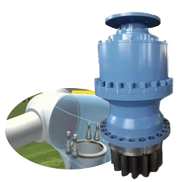
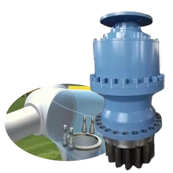
Buying a yaw drive is not about picking a ratio off a chart. It is about matching the peak yaw moment of your nacelle, the salt-fog class of your site, and the flange of the motor you already have on the shelf. Raydafon builds this yaw drive planetary gearbox in twelve frame sizes so that onshore and offshore OEMs can specify a unit that bolts straight onto the tower without re-machining the interface. Send us your nacelle load case and we return a matched drawing — not a catalogue page.

A yaw drive spends its life holding a rotor into the wind, correcting small angles thousands of times per day under gust loading. That duty cycle punishes the gear teeth and the seal far more than a continuous-running transmission does. Four design decisions on this unit address that directly.
Multi-stage planetary layout splits input torque across every planet in mesh, cutting the single-tooth surface load by roughly 40 % compared with a parallel-shaft arrangement. On a 3 MW machine the peak moment is spread over several contact paths instead of one, which is what keeps pitting away from the tooth flanks after years of yaw corrections.
Alloy steel gears go through carburising and quenching, then profile modification to compensate for deflection under load. Surface hardness lands in the HRC 58–62 band with a tough core behind it. Dynamic noise measured on the test bench stays under 65 dB(A) — well below the 80 dB(A) typical of older yaw gearboxes. See our precision gear manufacturing page for the full process chain.
The housing is cast as a single ductile iron body (QT400-18AL), heat-treated to a tensile strength of about 600 MPa. No split lines means no path for moisture. A three-stage sealing arrangement — lip seal, labyrinth, and grease barrier — holds IP67 against salt spray, dust, and the −40 °C to +60 °C swing seen on North Sea and desert sites alike.
Vibration and bearing-temperature sensors can be specified as an option and are read through an edge module that flags drift roughly 72 hours before a hard failure. Bearings are relubricable and seals are maintenance-free, so the module can be pulled and refitted on the tower. Modular assembly cuts single service downtime by around 60 % versus a traditional stack.
| Output torque range | 1,000 – 80,000 N·m |
| Gear ratios | i = 300 – 2,000 |
| Support | Slew bearing support, flange mounted |
| Electric brake | DC and AC type |
| Output shaft | Splined or with integral pinion; output shafts supported by heavy-duty capacity bearings |
| Applicable motors | IEC electric motors |
Frame size, ratio and brake type are selected against your nacelle yaw moment and motor flange. If your site carries a high turbulence class, ask for the derated torque column.
| Type | Nominal Output Torque (N·m) | Peak Static Output Torque (N·m) | Ratio (i) |
|---|---|---|---|
| 700L | 1,000 | 2,000 | 297 – 2,153 |
| 701L | 2,000 | 4,000 | 297 – 2,153 |
| 703AL | 2,500 | 5,000 | 278 – 1,866 |
| 705AL | 5,000 | 10,000 | 278 – 1,866 |
| 706BL4 | 8,000 | 15,000 | 203 – 2,045 |
| 707AL4 | 12,000 | 25,000 | 278 – 1,856 |
| 709AL4 | 18,000 | 30,000 | 278 – 1,856 |
| 711BL4 | 35,000 | 80,000 | 256 – 1,606 |
| 710L4 | 25,000 | 50,000 | 329 – 1,420 |
| 711L4 | 35,000 | 80,000 | 256 – 1,606 |
| 713L3 | 50,000 | 100,000 | 250 – 1,748 |
| 715L4 | 80,000 | 140,000 | 269 – 1,390 |
Not sure which frame fits? Send your nacelle diameter, yaw motor power and required yaw speed to our engineering desk and we will return the matching type within three working days.
The yaw motor drives the sun gear, which is the power input end of the train. Because the sun gear is small relative to the ring gear, it turns fast and carries low torque — which is exactly what an IEC motor is good at.
Three or four planet gears mesh simultaneously with the sun gear and with the internal ring gear. Each planet rotates on its own bearing while revolving around the sun, so the load is shared rather than concentrated on a single tooth pair.
The carrier collects the orbital motion of every planet and passes it to the output shaft — splined or with an integral pinion — which drives the slewing ring and turns the nacelle. Reduction is set by the tooth counts of the ring and sun plus the number of planets in mesh.
When wind force makes the yaw moment fluctuate, a floating carrier design lets the gears reposition slightly so at least three teeth stay in contact. Bench and field data show transmission error staying inside 0.08° under ±12 % moment fluctuation, against roughly 0.3° for a conventional parallel-shaft unit. Elastic support — high-damping rubber combined with metal shims — takes the high-frequency shock out before it reaches the tooth flank.
Rotating gears throw oil onto the housing oil channel while a pump feeds the planet bearings at around 8 L/min. At −25 °C the system still holds viscosity inside the ISO VG 320 band, so gears do not scuff on a cold start. A spiral oil channel paired with cooling fins carries heat to the housing; under continuous yaw duty the oil sump stays below 60 °C, about 12 °C cooler than a conventional layout, which slows lubricant ageing.
“Eighteen months on a North Sea platform with no failure. The sealing and anti-corrosion design cut our maintenance spend by about 40 %, and the yaw response under typhoon conditions is roughly 25 % quicker than the units we ran before. Nacelle positioning holds at ±0.15°, which lifted annual generation by close to 8 %. When a motor-matching issue came up, their engineers resolved it remotely in three hours.”
Hans Müller Technical Procurement Manager, EnerWind Energy Group, Germany“We retrofitted a 3 MW site in the California desert with these yaw drives. They handle a 60 °C day-night swing, run about 30 % quieter than the old gearboxes, and hold ±0.1° positioning — that alone moved generation efficiency up 7 %. The after-sales team runs quarterly inspections and swapped out worn lubricant filters before they became a problem.”
Lucas Thompson GreenPower Renewables, United States“Six months into a Scottish offshore project at an average 12 m/s wind speed: zero leakage, zero abnormal noise, and a yaw response about 20 % faster than the original solution, which added 9 % to wind efficiency. Their technical team stayed with us from commissioning through data monitoring and even re-tuned the lubrication parameters, which should add around 15 % to service life.”
Ethan Carter WindHorizon Energy, United KingdomTell us your nacelle yaw moment, motor frame and site corrosion class. We will reply with a recommended frame size, a 2D interface drawing and a factory-direct quotation — usually within 24 hours. Full range available on our wind turbine gearbox page, or browse the wider planetary gearbox series.
Request a Factory QuoteAddress
Luotuo Industrial Area, Zhenhai District, Ningbo City, China
Tel
+86-574-87168065
Luotuo Industrial Area, Zhenhai District, Ningbo City, China